Figures & data
Figure 1. Operating room set-up. A: Markings on the distal femur representing osteochondral lesions. B: Arthroscopy is used to determine the locations of the markings with a (navigated) pointer. C and D: Set-up for arthroscopically assisted retrograde drilling controlled by 2D fluoroscopy (group 1) or the Fluoro Free navigation technique (group 2).
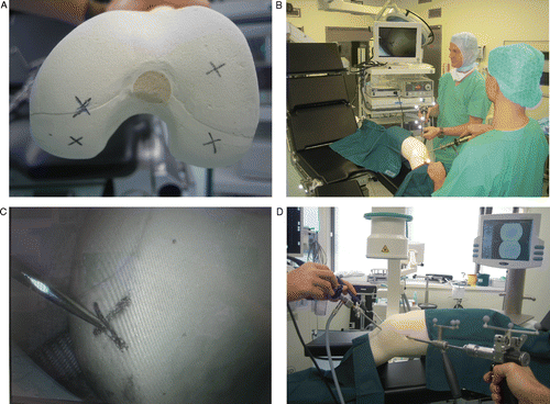
Figure 2. Postoperative fluoroscopic control images are acquired after retrograde drillings in both groups.
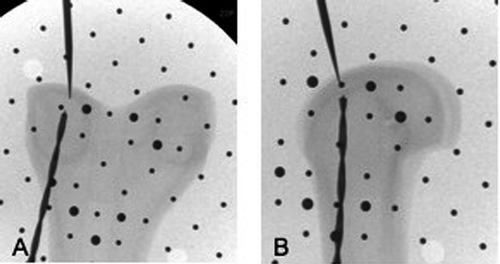
Figure 3. The sterile touch-screen of the navigation system displays navigated instruments in three different projections. The labeled items are (a) the sleeve; (b) the drill bit, including the offset (red) and the potential deviation zone at the tip of the drill bit (green cone); (c) the pointer (green) with offset (red); and (d) the virtual center of the osteochondral lesion.
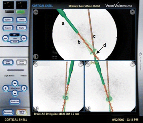
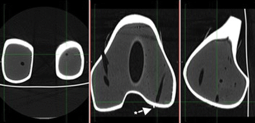
Figure 4. Image processing and vector calculation was performed based on postoperative CT scans in the three planes of the drilling axis in the femoral condyles. In the center panel, the star indicates a metal ball applied to enable visualization of the marked osteochondral lesion in the CT scans.