584
Views
2
CrossRef citations to date
0
Altmetric
Research Article

A potential means of improving the evaluation of deformity corrections with Taylor Spatial Frames over time by using volumetric imaging: Preliminary results

, , , Ph.D., , &
Pages 100-108 | Received 29 Nov 2008, Accepted 28 Oct 2009, Published online: 06 Jan 2010

Figures & data

Figure 1. Flow chart showing the procedure followed to obtain the final numerical measurement. The results presented in this paper illustrate the general algorithm (especially in the case of patient 2) and prove that each step can be performed successfully.
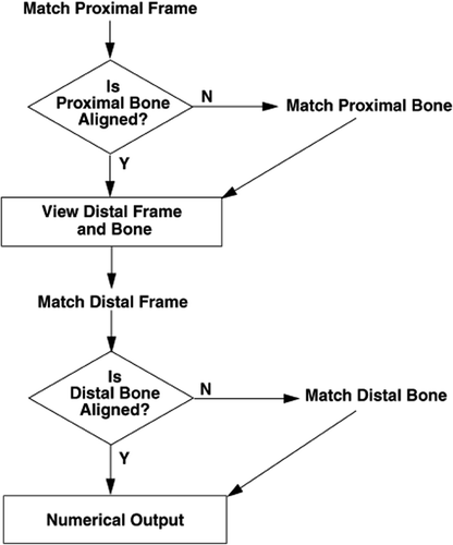
Figure 1. Flow chart showing the procedure followed to obtain the final numerical measurement. The results presented in this paper illustrate the general algorithm (especially in the case of patient 2) and prove that each step can be performed successfully.

Figure 2. (a) The top frames (white arrows) for patient 1 are nicely aligned (green and yellow frame surfaces coincide), but the proximal tibia (magenta arrows) is not aligned (yellow: original CT-A volume from first scan date; green: original CT-B volume from second scan date after registration–FVOL-1). The top frame and pins were moved between the first (CT-A) and second (CT-B) scans. (b) The distal tibia is now well aligned (white arrow). Bony landmarks were used on the original CT-A and CT-B volumes to register the proximal tibia, and the resulting fused volume (FVOL-2) was used together with bony landmarks on the original CT-A volume to register the distal tibia, resulting in FVOL-3 (yellow: FVOL-3; green: original CT-A volume from first scan date).
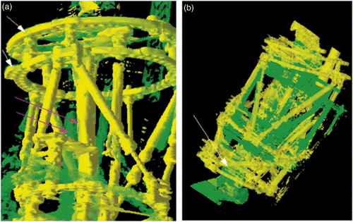
Figure 2. (a) The top frames (white arrows) for patient 1 are nicely aligned (green and yellow frame surfaces coincide), but the proximal tibia (magenta arrows) is not aligned (yellow: original CT-A volume from first scan date; green: original CT-B volume from second scan date after registration–FVOL-1). The top frame and pins were moved between the first (CT-A) and second (CT-B) scans. (b) The distal tibia is now well aligned (white arrow). Bony landmarks were used on the original CT-A and CT-B volumes to register the proximal tibia, and the resulting fused volume (FVOL-2) was used together with bony landmarks on the original CT-A volume to register the distal tibia, resulting in FVOL-3 (yellow: FVOL-3; green: original CT-A volume from first scan date).

Figure 3. Weight points for registered distal tibia of patient 1. (a) Axial, coronal, and sagittal slices from the original CT-A volume from the first scan date. (b) Axial, coronal, and sagittal slices from the FVOL-3 volume derived from registering the distal tibia from FVOL-2 (proximal tibia registered) with the original (CT-A) distal tibia. The weight points, derived from the landmarks, are shown on each slice (white arrows). Over the period of 33 weeks, the elongation of the tibia was approximately 34 mm and the rotation was approximately 10°.
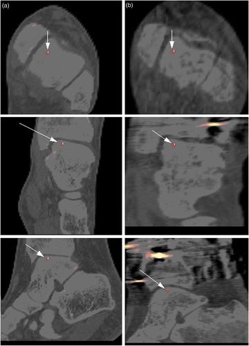
Figure 3. Weight points for registered distal tibia of patient 1. (a) Axial, coronal, and sagittal slices from the original CT-A volume from the first scan date. (b) Axial, coronal, and sagittal slices from the FVOL-3 volume derived from registering the distal tibia from FVOL-2 (proximal tibia registered) with the original (CT-A) distal tibia. The weight points, derived from the landmarks, are shown on each slice (white arrows). Over the period of 33 weeks, the elongation of the tibia was approximately 34 mm and the rotation was approximately 10°.

Figure 4. (a) For patient 2, the top frame and proximal tibia are well aligned when the top frame only is used for the registration (FVOL-1) (yellow: CT-A from first scan date; green: FVOL-1). However, the proximal pins (white arrows) are clearly not aligned. (b) The proximal tibia and pins are then used to align the proximal tibia (FVOL-3). This results in the pins (white arrow) and proximal tibia being better aligned, but the top frame (magenta arrow) is no longer aligned (yellow: CT-A from first date; green: FVOL-3).
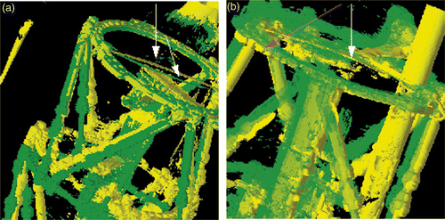
Figure 4. (a) For patient 2, the top frame and proximal tibia are well aligned when the top frame only is used for the registration (FVOL-1) (yellow: CT-A from first scan date; green: FVOL-1). However, the proximal pins (white arrows) are clearly not aligned. (b) The proximal tibia and pins are then used to align the proximal tibia (FVOL-3). This results in the pins (white arrow) and proximal tibia being better aligned, but the top frame (magenta arrow) is no longer aligned (yellow: CT-A from first date; green: FVOL-3).

Figure 5. Left panels: Axial view (a) and sagittal view (c) showing the registered top frame for patient 2 (FVOL-1). The proximal tibia, however, is not quite in alignment, nor are the pins. Right panels: Axial view (b) and sagittal view (d) after registering the proximal tibia using landmarks only on the proximal tibia and pins (FVOL-3).
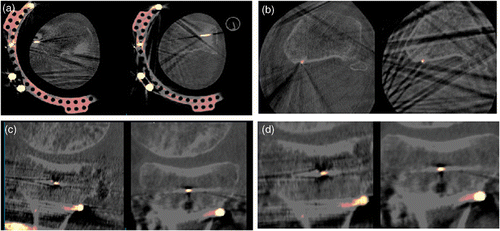
Figure 5. Left panels: Axial view (a) and sagittal view (c) showing the registered top frame for patient 2 (FVOL-1). The proximal tibia, however, is not quite in alignment, nor are the pins. Right panels: Axial view (b) and sagittal view (d) after registering the proximal tibia using landmarks only on the proximal tibia and pins (FVOL-3).

Figure 6. (a) The fused proximal volume (FVOL-3) for patient 2 was used to align the bottom frame (yellow: fused distal volume (FVOL-4); green: original CT-A volume from first scan date). Both the bottom frame and the distal tibia (white arrows) are well aligned. The bottom pins (magenta arrow) are slightly off, but not nearly as much as at the top. (b) The fused distal volume (FVOL-4) was used with bony landmarks to further align the distal tibia (FVOL-5). The distal frame, distal tibia (white arrows) and pins (magenta arrow) are all well aligned (yellow: FVOL-5; green: original CT-A volume from first scan date).
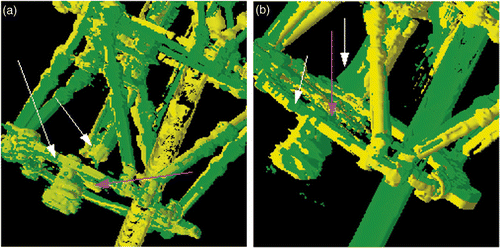
Figure 6. (a) The fused proximal volume (FVOL-3) for patient 2 was used to align the bottom frame (yellow: fused distal volume (FVOL-4); green: original CT-A volume from first scan date). Both the bottom frame and the distal tibia (white arrows) are well aligned. The bottom pins (magenta arrow) are slightly off, but not nearly as much as at the top. (b) The fused distal volume (FVOL-4) was used with bony landmarks to further align the distal tibia (FVOL-5). The distal frame, distal tibia (white arrows) and pins (magenta arrow) are all well aligned (yellow: FVOL-5; green: original CT-A volume from first scan date).

Figure 7. Weight points for registered tibia of patient 2. Column (a): Axial, coronal, and sagittal slices from original CT-A volume from first scan date. Column (b): Axial, coronal, and sagittal slices from volume derived from final registration, FVOL-5, of distal tibia. The weight points, derived from the landmarks, are shown (white arrows) on each slice. Over the period of 5 weeks, the elongation of the tibia was approximately 5 mm and the rotation was approximately 1°.
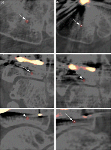
Figure 7. Weight points for registered tibia of patient 2. Column (a): Axial, coronal, and sagittal slices from original CT-A volume from first scan date. Column (b): Axial, coronal, and sagittal slices from volume derived from final registration, FVOL-5, of distal tibia. The weight points, derived from the landmarks, are shown (white arrows) on each slice. Over the period of 5 weeks, the elongation of the tibia was approximately 5 mm and the rotation was approximately 1°.

Reprints and Corporate Permissions

Please note: Selecting permissions does not provide access to the full text of the article, please see our help page How do I view content?

To request a reprint or corporate permissions for this article, please click on the relevant link below:

Academic Permissions

Please note: Selecting permissions does not provide access to the full text of the article, please see our help page How do I view content?

Obtain permissions instantly via Rightslink by clicking on the button below:

If you are unable to obtain permissions via Rightslink, please complete and submit this Permissions form. For more information, please visit our Permissions help page.