1,643
Views
37
CrossRef citations to date
0
Altmetric
Biomedical Papers

Integration of CAD/CAM planning into computer assisted orthopaedic surgery

, , , , &
Pages 65-74 | Received 31 Jul 2009, Accepted 31 May 2010, Published online: 20 Sep 2010

Figures & data

Figure 1. Workflow for integrating CAD/CAM planning into computer assisted orthopaedic surgery.

Figure 1. Workflow for integrating CAD/CAM planning into computer assisted orthopaedic surgery.

Figure 2. Periacetabular osteotomies (red planes) were planned on a virtual 3D pelvic model generated from the patient's CT data using MIMICS software (A). The acetabular bone segment (blue) was virtually realigned until the measured acetabular angle was adequate or equal to that on the opposite side (B). The resulting bone defect created above the acetabulum (red arrow in B) could be measured and its dimensions used to guide the harvesting of a bone graft from the ipsilateral iliac crest (C). A postoperative plain radiograph (D) showed good fitting of the bone graft and alignment of the acetabulum (dotted line).
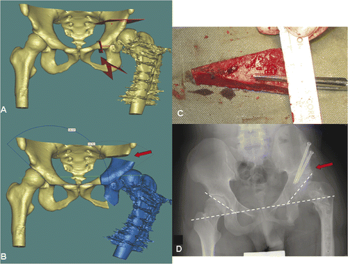
Figure 2. Periacetabular osteotomies (red planes) were planned on a virtual 3D pelvic model generated from the patient's CT data using MIMICS software (A). The acetabular bone segment (blue) was virtually realigned until the measured acetabular angle was adequate or equal to that on the opposite side (B). The resulting bone defect created above the acetabulum (red arrow in B) could be measured and its dimensions used to guide the harvesting of a bone graft from the ipsilateral iliac crest (C). A postoperative plain radiograph (D) showed good fitting of the bone graft and alignment of the acetabulum (dotted line).

Figure 3. Preoperative display of the surgical planning for Patient 1 on the navigation monitor. Coronal (A) and sagittal (C) images showed image fusion of CT data sets with virtual osteotomies (representing the pelvic model in ) and the original CT data sets. The fusion images helped to locate exactly the planned planes of the osteotomies, which were then marked with virtual screws (C). Coronal images (B) illustrated image fusion of CT data sets with virtual realignment (representing the pelvic model in ) and the original CT data sets. The planes of the periacetabular osteotomies were marked with virtual screws on the reconstructed 3D pelvic model (D). For the actual operation, following surgical exposure of the acetabulum and insertion of a tracker into the iliac crest, image-to-patient registration was performed on the original CT datasets. The osteotomy planes were defined by locating the positions of the virtual screws under navigational guidance. The pelvic bone was then osteotomized with an oscillating saw and osteotomes. The acetabular bone segment was realigned to open a bone defect above the acetabulum, and an iliac crest bone graft () was inserted into this defect. On toggling the fusion image to CT datasets with virtual realignment, the surface of the mobilized acetabular bone segment was traced by a navigation pointer. The position of the acetabulum was adjusted and assessed to be optimal if it matched with its corresponding position on the CT datasets with virtual realignment. The acetabular segment was then temporarily secured to the iliac bone with K-wires. The bone graft was fixed with two 6.5-mm cannulated titanium screws under navigational guidance () which helped to avoid penetration into the hip joint.
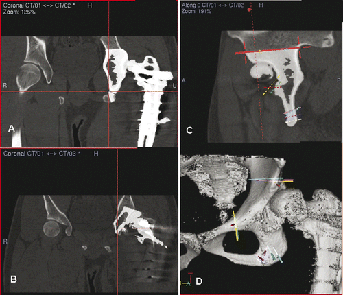
Figure 3. Preoperative display of the surgical planning for Patient 1 on the navigation monitor. Coronal (A) and sagittal (C) images showed image fusion of CT data sets with virtual osteotomies (representing the pelvic model in Figure 2A) and the original CT data sets. The fusion images helped to locate exactly the planned planes of the osteotomies, which were then marked with virtual screws (C). Coronal images (B) illustrated image fusion of CT data sets with virtual realignment (representing the pelvic model in Figure 2B) and the original CT data sets. The planes of the periacetabular osteotomies were marked with virtual screws on the reconstructed 3D pelvic model (D). For the actual operation, following surgical exposure of the acetabulum and insertion of a tracker into the iliac crest, image-to-patient registration was performed on the original CT datasets. The osteotomy planes were defined by locating the positions of the virtual screws under navigational guidance. The pelvic bone was then osteotomized with an oscillating saw and osteotomes. The acetabular bone segment was realigned to open a bone defect above the acetabulum, and an iliac crest bone graft (Figure 2C) was inserted into this defect. On toggling the fusion image to CT datasets with virtual realignment, the surface of the mobilized acetabular bone segment was traced by a navigation pointer. The position of the acetabulum was adjusted and assessed to be optimal if it matched with its corresponding position on the CT datasets with virtual realignment. The acetabular segment was then temporarily secured to the iliac bone with K-wires. The bone graft was fixed with two 6.5-mm cannulated titanium screws under navigational guidance (Figure 2D) which helped to avoid penetration into the hip joint.

Figure 4. For Patient 2, a 3D model of the left tibial fracture non-union with deformity was generated from the MIMICS software (A). The plane of the osteotomy (red) was then planned at the fracture line in the reconstructed 3D tibial model (B).
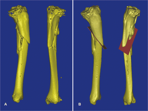
Figure 4. For Patient 2, a 3D model of the left tibial fracture non-union with deformity was generated from the MIMICS software (A). The plane of the osteotomy (red) was then planned at the fracture line in the reconstructed 3D tibial model (B).

Figure 5. In a virtual simulation of a corrective osteotomy, the proximal and distal segments of the tibia were separated. The distal tibia (yellow) was mobilized from its original deformed position to its corrected position (gray). The final position was determined by assessing the mechanical axis of the two tibial segments, the continuity of the anterior tibial crest, and also the knee and ankle joint lines. The deformity could then be quantified, and was measured as 11° procurvatum (A), 7° varus (B) and 9° rotational deformity (C). To facilitate the deformity correction, parallel alignment pins were planned at the proximal tibia (two red pins) and the distal tibia in the corrected position (two green pins). The distal tibia (gray) and the green alignment pins were moved together and back to the original deformed position. The locations of the distal alignment pins on the deformed distal tibia (two red pins) were defined.
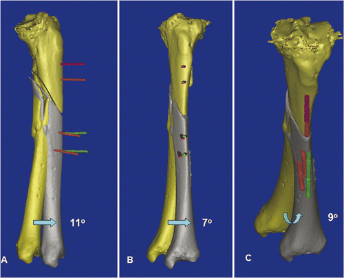
Figure 5. In a virtual simulation of a corrective osteotomy, the proximal and distal segments of the tibia were separated. The distal tibia (yellow) was mobilized from its original deformed position to its corrected position (gray). The final position was determined by assessing the mechanical axis of the two tibial segments, the continuity of the anterior tibial crest, and also the knee and ankle joint lines. The deformity could then be quantified, and was measured as 11° procurvatum (A), 7° varus (B) and 9° rotational deformity (C). To facilitate the deformity correction, parallel alignment pins were planned at the proximal tibia (two red pins) and the distal tibia in the corrected position (two green pins). The distal tibia (gray) and the green alignment pins were moved together and back to the original deformed position. The locations of the distal alignment pins on the deformed distal tibia (two red pins) were defined.

Figure 6. After placing a patient tracker on the proximal tibia and performing image-to-patient registration, proximal and distal alignments pins were inserted into the corresponding tibial segments under navigational guidance (A). The plane of the tibial osteotomy was identified and marked according to the navigation planning, and the osteotomy performed using an oscillating saw. The distal tibial segment was then realigned until the proximal and distal alignment pins were parallel and stabilized with an external fixator (B). A navigation probe was run along the surface of the realigned distal tibia, and the tip of the probe matched with the bone surface of the realigned tibia in the virtual navigation plan in the coronal (C), axial (D) and sagittal (E) images, thereby indirectly navigating and confirming the final corrected position of the distal tibial segment. The reconstructed 3D tibia model (F) was less useful for this validation because the CT Spine Navigation software was unable to segment and display the virtual distal tibia with the corrected position. A postoperative plain radiograph of the tibia showed satisfactory alignment and a healed osteotomy at 5 months following surgery (G).
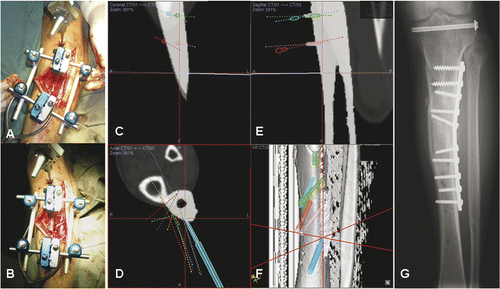
Figure 6. After placing a patient tracker on the proximal tibia and performing image-to-patient registration, proximal and distal alignments pins were inserted into the corresponding tibial segments under navigational guidance (A). The plane of the tibial osteotomy was identified and marked according to the navigation planning, and the osteotomy performed using an oscillating saw. The distal tibial segment was then realigned until the proximal and distal alignment pins were parallel and stabilized with an external fixator (B). A navigation probe was run along the surface of the realigned distal tibia, and the tip of the probe matched with the bone surface of the realigned tibia in the virtual navigation plan in the coronal (C), axial (D) and sagittal (E) images, thereby indirectly navigating and confirming the final corrected position of the distal tibial segment. The reconstructed 3D tibia model (F) was less useful for this validation because the CT Spine Navigation software was unable to segment and display the virtual distal tibia with the corrected position. A postoperative plain radiograph of the tibia showed satisfactory alignment and a healed osteotomy at 5 months following surgery (G).

Figure 7. For Patient 3, sagittal (A) and coronal (B) MR images showed a low-grade parosteal osteosarcoma involving the right distal femur. The tumor mainly involved the anterior part of the medial femoral condyle; the lateral and posteromedial femoral condyles were spared. It was therefore possible to precisely plan a multi-planar resection that preserved the lateral collateral ligaments at the lateral femoral condyle and also the insertion of the cruciate ligments at the femoral intercondylar notch. These soft tissue attachments are important for knee stability and the blood supply of the distal femur bone remnants when a joint-sparing tumor resection and reconstruction is contemplated. The resection was planned and simulated on the reconstructed 3D distal femur model in the MIMICS software (C).
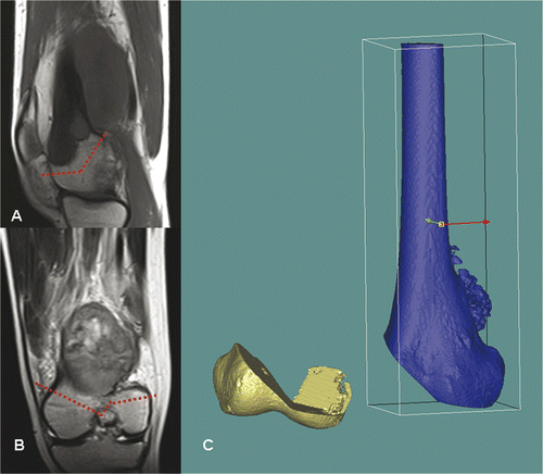
Figure 7. For Patient 3, sagittal (A) and coronal (B) MR images showed a low-grade parosteal osteosarcoma involving the right distal femur. The tumor mainly involved the anterior part of the medial femoral condyle; the lateral and posteromedial femoral condyles were spared. It was therefore possible to precisely plan a multi-planar resection that preserved the lateral collateral ligaments at the lateral femoral condyle and also the insertion of the cruciate ligments at the femoral intercondylar notch. These soft tissue attachments are important for knee stability and the blood supply of the distal femur bone remnants when a joint-sparing tumor resection and reconstruction is contemplated. The resection was planned and simulated on the reconstructed 3D distal femur model in the MIMICS software (C).

Figure 8. A CAD custom joint-saving prosthesis of the distal femur (C) was designed and manufactured based on the exact dimensions of the bone defect created in the virtual tumor resection. Posterior (A) and anterior (B) views of the 3D CAD model of the planned reconstruction are shown. With the help of this model, surgeons and implant engineers could discuss more effectively the choice of fixation at the distal prosthetic junction (length/direction of screws and extracortical plates). The CAD design and the actual prosthesis at the distal junction are shown in (D) and (E), respectively. The cutting flutes provided additional stability for fixation, and a coating of hydroxyapatite (white) was used to facilitate osteointegration at the proximal and distal prosthetic junctions.
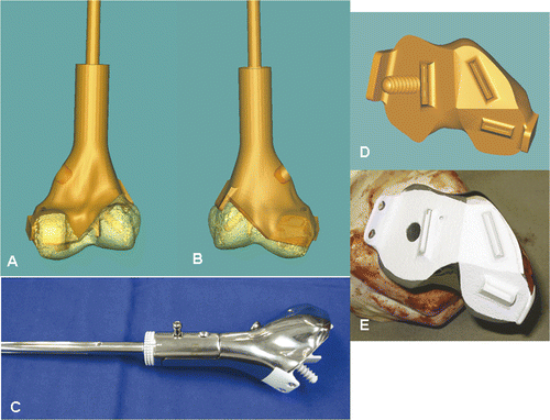
Figure 8. A CAD custom joint-saving prosthesis of the distal femur (C) was designed and manufactured based on the exact dimensions of the bone defect created in the virtual tumor resection. Posterior (A) and anterior (B) views of the 3D CAD model of the planned reconstruction are shown. With the help of this model, surgeons and implant engineers could discuss more effectively the choice of fixation at the distal prosthetic junction (length/direction of screws and extracortical plates). The CAD design and the actual prosthesis at the distal junction are shown in (D) and (E), respectively. The cutting flutes provided additional stability for fixation, and a coating of hydroxyapatite (white) was used to facilitate osteointegration at the proximal and distal prosthetic junctions.

Figure 9. Preoperative screen images of surgical navigation planning on the navigation monitor. (A) shows the extent of the tumor (red dotted line) in the sagittal-view CT-MR image fusion. As back-conversion of the prosthesis from CAD to DICOM format was possible, the CAD prosthesis could be integrated into the navigation planning by CT-CT/prosthesis image fusion. Axial (B) and coronal (C) images illustrate the appearance of the prosthesis (in white) in the planning. This integration greatly facilitated the precise definition of multi-planar osteotomies at the distal femur. (D) shows the reconstructed 3D bone tumor model with the planes of resection defined by virtual pedicle screws. Use of CAD/CAM surgical planning and intraoperative navigational guidance enabled accurate tumor resection and precise fitting of the complex CAD prosthesis, as confirmed by postoperative plain radiographs (E and F).
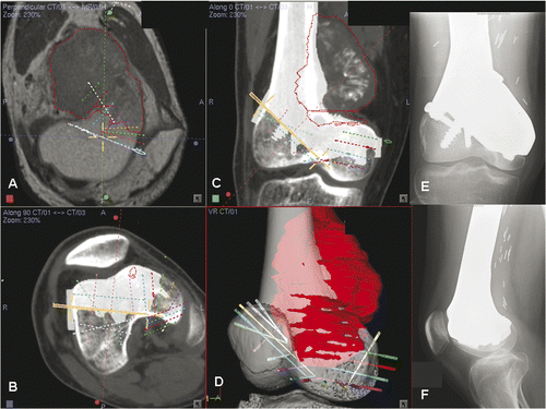
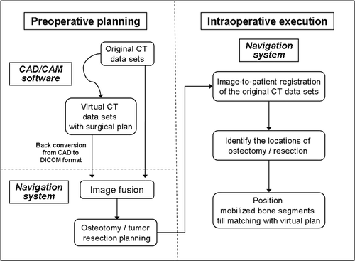
Figure 9. Preoperative screen images of surgical navigation planning on the navigation monitor. (A) shows the extent of the tumor (red dotted line) in the sagittal-view CT-MR image fusion. As back-conversion of the prosthesis from CAD to DICOM format was possible, the CAD prosthesis could be integrated into the navigation planning by CT-CT/prosthesis image fusion. Axial (B) and coronal (C) images illustrate the appearance of the prosthesis (in white) in the planning. This integration greatly facilitated the precise definition of multi-planar osteotomies at the distal femur. (D) shows the reconstructed 3D bone tumor model with the planes of resection defined by virtual pedicle screws. Use of CAD/CAM surgical planning and intraoperative navigational guidance enabled accurate tumor resection and precise fitting of the complex CAD prosthesis, as confirmed by postoperative plain radiographs (E and F).

Reprints and Corporate Permissions

Please note: Selecting permissions does not provide access to the full text of the article, please see our help page How do I view content?

To request a reprint or corporate permissions for this article, please click on the relevant link below:

Academic Permissions

Please note: Selecting permissions does not provide access to the full text of the article, please see our help page How do I view content?

Obtain permissions instantly via Rightslink by clicking on the button below:

If you are unable to obtain permissions via Rightslink, please complete and submit this Permissions form. For more information, please visit our Permissions help page.