1,185
Views
23
CrossRef citations to date
0
Altmetric
Research Article

Stress concentration near pin holes associated with fracture risk after computer navigated total knee arthroplasty

, , PhD, &
Pages 98-103 | Received 02 Sep 2009, Accepted 08 Jul 2010, Published online: 27 Sep 2010

Figures & data

Figure 1. Finite element model of a femur with loading and boundary conditions (A) and four different modes of pin penetration in tubular bone: unicortical (B), bicortical (C), half-bicortical, (D) and transcortical (E).
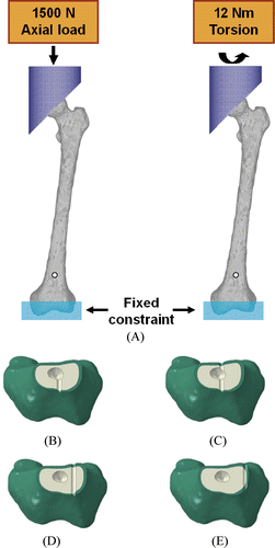
Figure 1. Finite element model of a femur with loading and boundary conditions (A) and four different modes of pin penetration in tubular bone: unicortical (B), bicortical (C), half-bicortical, (D) and transcortical (E).

Figure 2. The von Mises stresses under 12 Nm of torsional load at the femoral head for transcortical pin penetration with pin diameter of 4 mm.

Figure 2. The von Mises stresses under 12 Nm of torsional load at the femoral head for transcortical pin penetration with pin diameter of 4 mm.

Figure 3. Maximum von Mises stresses at the pin hole normalized to the maximum von Mises stresses in the intact model for different pin penetration modes and pin diameters for 1500 N of axial compressive load at the femoral head.
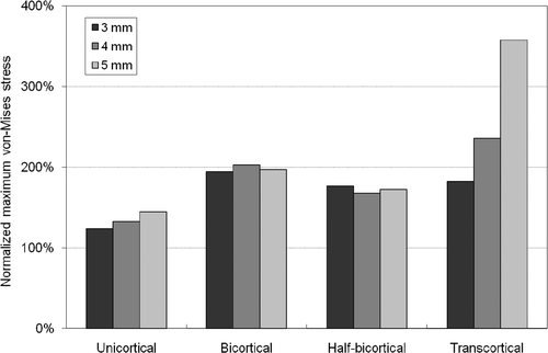
Figure 3. Maximum von Mises stresses at the pin hole normalized to the maximum von Mises stresses in the intact model for different pin penetration modes and pin diameters for 1500 N of axial compressive load at the femoral head.

Figure 4. Maximum von Mises stresses at the pin hole normalized to the maximum von Mises stresses in the intact model for different pin penetration modes and pin diameters for 12 Nm of torsional load at the femoral head.
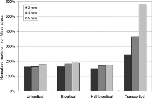
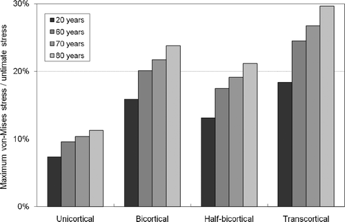
Figure 4. Maximum von Mises stresses at the pin hole normalized to the maximum von Mises stresses in the intact model for different pin penetration modes and pin diameters for 12 Nm of torsional load at the femoral head.
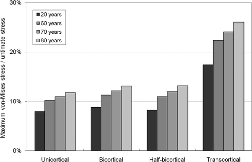
Figure 5. Ratio of maximum von Mises stress to ultimate stress at the pin hole in patient models of different ages for 1500 N of axial compressive load at the femoral head.

Figure 5. Ratio of maximum von Mises stress to ultimate stress at the pin hole in patient models of different ages for 1500 N of axial compressive load at the femoral head.

Figure 6. Ratio of maximum von Mises stress to ultimate stress at the pin hole in patient models of different ages for 12 Nm of torsional load at the femoral head.

Figure 6. Ratio of maximum von Mises stress to ultimate stress at the pin hole in patient models of different ages for 12 Nm of torsional load at the femoral head.

Reprints and Corporate Permissions

Please note: Selecting permissions does not provide access to the full text of the article, please see our help page How do I view content?

To request a reprint or corporate permissions for this article, please click on the relevant link below:

Academic Permissions

Please note: Selecting permissions does not provide access to the full text of the article, please see our help page How do I view content?

Obtain permissions instantly via Rightslink by clicking on the button below:

If you are unable to obtain permissions via Rightslink, please complete and submit this Permissions form. For more information, please visit our Permissions help page.