1,242
Views
6
CrossRef citations to date
0
Altmetric
Research Article

Comparison of three optical tracking systems in a complex navigation scenario

, & , PhD
Pages 104-109 | Received 23 Nov 2008, Accepted 24 Sep 2009, Published online: 12 Nov 2010

Figures & data

Figure 1. The Iso-C3D calibration procedure requires scanning of a special phantom containing radio-opaque markers. The calibration matrix TCal is determined for a certain start position of the Iso-C3D. The determination is done automatically by the Iso-C3D system software.
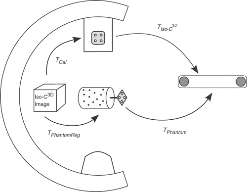
Figure 1. The Iso-C3D calibration procedure requires scanning of a special phantom containing radio-opaque markers. The calibration matrix TCal is determined for a certain start position of the Iso-C3D. The determination is done automatically by the Iso-C3D system software.

Figure 2. When scanning a subject, the navigation system can easily calculate the registration matrix TSubjectReg by measuring the transformations TSubject and TIso-C3D when the Iso-C3D is in its pre-calibrated start position. The complete navigation scenario is shown, including an abstract pointing tool.
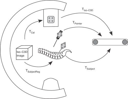
Figure 2. When scanning a subject, the navigation system can easily calculate the registration matrix TSubjectReg by measuring the transformations TSubject and TIso-C3D when the Iso-C3D is in its pre-calibrated start position. The complete navigation scenario is shown, including an abstract pointing tool.

Figure 3. The phantom used in the presented study. It is made of acrylic glass and carries 27 titanium markers arranged in a regular 3 × 3 grid. Here it is shown equipped with a passive reference base.
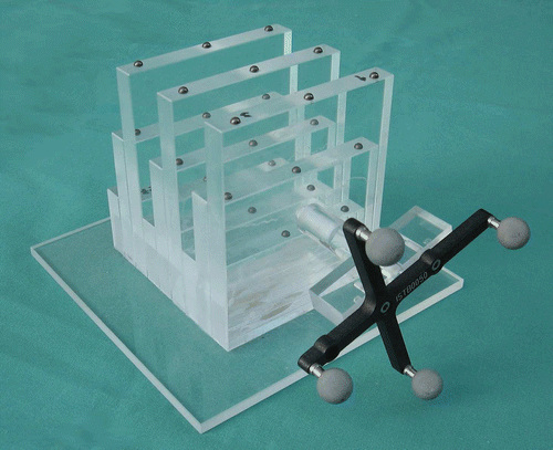
Figure 3. The phantom used in the presented study. It is made of acrylic glass and carries 27 titanium markers arranged in a regular 3 × 3 grid. Here it is shown equipped with a passive reference base.

Figure 4. The pointer used for digitizing the fiducial marker positions. In this case it is being used with an active reference base. The pointer has a hollow tip that matches the marker spheres exactly.
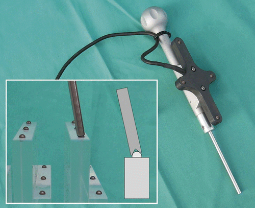
Figure 4. The pointer used for digitizing the fiducial marker positions. In this case it is being used with an active reference base. The pointer has a hollow tip that matches the marker spheres exactly.

Figure 5. Plot showing the distribution of the measured RMS errors summarized in . Note that the values for the Optotrak system at site 2 are based on only seven scans as opposed to 20 scans for the other cameras.
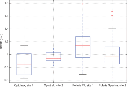
Figure 5. Plot showing the distribution of the measured RMS errors summarized in Table I. Note that the values for the Optotrak system at site 2 are based on only seven scans as opposed to 20 scans for the other cameras.

Table I.  Root mean square errors (RMSE) for the conducted experiments. In each experiment an Iso-C3D scan was performed and up to 27 fiducial marker positions were compared using the subject's registration matrix.

Reprints and Corporate Permissions

Please note: Selecting permissions does not provide access to the full text of the article, please see our help page How do I view content?

To request a reprint or corporate permissions for this article, please click on the relevant link below:

Academic Permissions

Please note: Selecting permissions does not provide access to the full text of the article, please see our help page How do I view content?

Obtain permissions instantly via Rightslink by clicking on the button below:

If you are unable to obtain permissions via Rightslink, please complete and submit this Permissions form. For more information, please visit our Permissions help page.