902
Views
14
CrossRef citations to date
0
Altmetric
Research Article

Comparison of multilevel oblique corpectomy with and without image guided navigation for multi-segmental cervical spondylotic myelopathy

, MD, PhD, , , , , & show all
Pages 32-37 | Received 24 May 2010, Accepted 22 Oct 2010, Published online: 08 Dec 2010

Figures & data

Table I.  Demographic and clinical data of patients. For mean values, ranges are in parentheses.

Figure 1. The longus colli muscle was retracted by a lateral blade connected to one of the central screws. Left: Anterior-posterior view with C-arm. Center: Lateral view with C-arm. Right: Microscopic view during contralateral-side drilling.
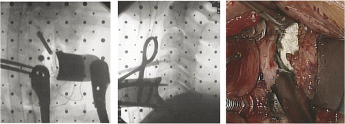
Figure 1. The longus colli muscle was retracted by a lateral blade connected to one of the central screws. Left: Anterior-posterior view with C-arm. Center: Lateral view with C-arm. Right: Microscopic view during contralateral-side drilling.

Figure 2. Left: A dynamic navigation frame was attached to the operating table with an external frame. In this configuration, navigation can be implemented while maintaining the microscopic view. Right: IGN is useful in the axial plane and also in the sagittal plane.
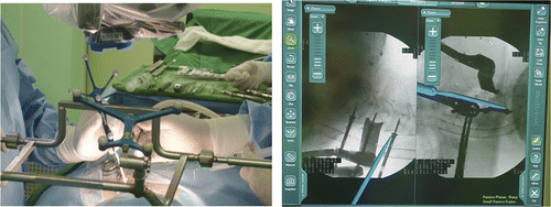
Figure 2. Left: A dynamic navigation frame was attached to the operating table with an external frame. In this configuration, navigation can be implemented while maintaining the microscopic view. Right: IGN is useful in the axial plane and also in the sagittal plane.

Figure 3. Preoperative and postoperative sagittal T2 images of a 62-year-old male with OPLL. Left: The upper and lower arrows indicate the direction of drilling. Right: The anterior portion of the upper and lower end segments was preserved.
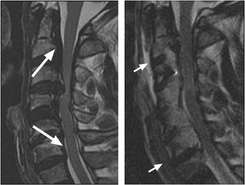
Figure 3. Preoperative and postoperative sagittal T2 images of a 62-year-old male with OPLL. Left: The upper and lower arrows indicate the direction of drilling. Right: The anterior portion of the upper and lower end segments was preserved.

Figure 4. Left: The arrow indicates the center of the vertebral body. The two lines represent the ideal trapezoid bony resection. Right: A is the remaining posterior body in millimeters from the ipsilateral medial margin of the pedicle; B is the same portion from the opposite side; and C is the remaining body from the center.
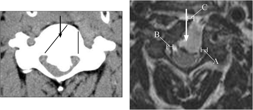
Figure 4. Left: The arrow indicates the center of the vertebral body. The two lines represent the ideal trapezoid bony resection. Right: A is the remaining posterior body in millimeters from the ipsilateral medial margin of the pedicle; B is the same portion from the opposite side; and C is the remaining body from the center.

Table II.  Completeness of multilevel oblique corpectomy (CMOC): mean values with ranges in parentheses (all measurements are in mm).

Table III.  Dispersion of treated levels.

Reprints and Corporate Permissions

Please note: Selecting permissions does not provide access to the full text of the article, please see our help page How do I view content?

To request a reprint or corporate permissions for this article, please click on the relevant link below:

Academic Permissions

Please note: Selecting permissions does not provide access to the full text of the article, please see our help page How do I view content?

Obtain permissions instantly via Rightslink by clicking on the button below:

If you are unable to obtain permissions via Rightslink, please complete and submit this Permissions form. For more information, please visit our Permissions help page.