Figures & data
Figure 1. 3D model of the cervical vertebra. (a) Posterior view. (b) Superior view.
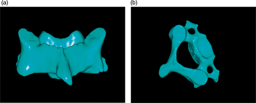
Figure 2. Analysis of cervical pedicle screw trajectory by the reverse engineering software. (a) Pedicle and its positive projection. (b) Best trajectory of pedicle screw projection. (c) Pedicle screw channel (arrow). (d) Planned screw trajectories (arrows).
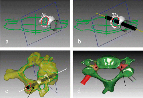
Figure 3. Design of the navigational template.
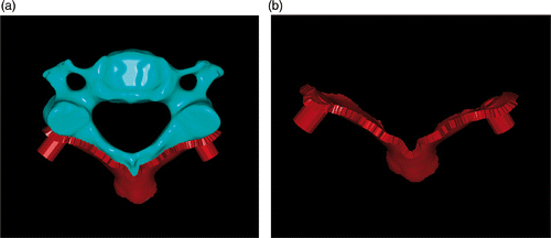
Figure 4. (a) Cervical spine specimen. (b) 3D reconstruction of cervical spine. (c) Drill template and corresponding cervical vertebrae. (d) Physical biomodel of the navigational template from C1–C7.
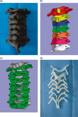
Figure 5. (a) The navigational templates fitted perfectly onto the posterior surface of their corresponding vertebrae. (b) A high-speed drill was used along the navigational channel to drill the trajectory of the pedicle screw. (c) Pedicle channel of cervical spine specimen. (d) Pedicle screws inserted into the cervical spine specimens.
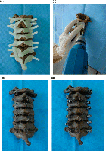
Figure 6. Postoperative CT scan showing good positioning of the cervical pedicle screw. (a) C2 pedicle screw – axial view. (b) C4 pedicle screw – axial view. (c) Sagittal view of cervical pedicle screw. (d) Coronal view of cervical pedicle screw.
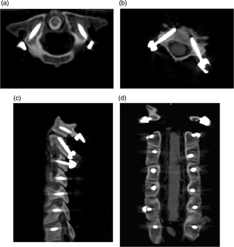
Table I. Number and incidence of pedicle perforations.