Figures & data
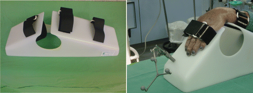
Figure 1. Stable immobilization of the forearm was assured by a specially developed splint for the dorsal intervention made from radiolucent material. The tracker for the 2D and 3D navigation could easily be positioned on this splint.

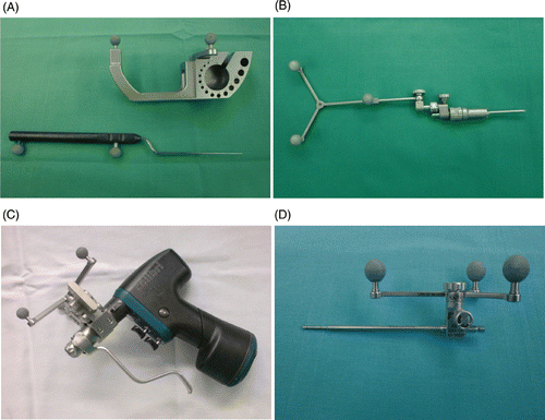
Figure 2. The instruments for the navigation. (A) Calibration device with the calibrated pointer. (B) Tracker for 2D and 3D navigation that can be attached to the splint. (C) Surgical motor, equipped with reflective marker spheres to enable its calibration and thereby its recognition by the optic localization system. (D) Drill guide, also equipped with marker spheres.

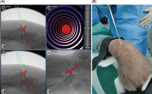
Figure 3. Pin insertion using 2D fluoroscopic navigation. (A) The computer screen displays three views of the wrist: lateral, oblique, and anteroposterior. The surgeon first determines the ideal trajectory of the screw along the scaphoid axis in all 3 planes. The exact position of the screw can then be reproduced with the navigated drill guide. The view at lower right enables alignment parallel to the planned implant position to be maintained in all available projections. Pin insertion can now begin. In this case, the direction of the drill was first imitated by using a calibrated pointer applied to the scaphoid tubercle. (B) Application of the calibrated pointer to the scaphoid in the cadaver.

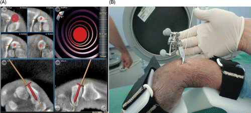
Figure 4. (A) Navigation screen for the 3D-navigated screw insertion. The presentation of multiplanar reconstructions allows exact positioning of the screw with respect to the drill. The head of the red screw corresponds to the end of the instrument to be navigated. The solid line indicates the extended virtual direction of the drill guide. (B) The navigated drill guide with the K-wire already inserted.

Figure 5. Method for calculating precision of screw placement on the basis of anteroposterior (AP) and lateral X-ray images of the scaphoid following the calculation by Liverneaux et al. Citation[6]. The gray line represents the scaphoid axis and the white line the screw axis. (A) Angle α represents the angle between the scaphoid axis and the screw axis in an AP X-ray image; α is positive when the entry point of the screw is medial in relation to the axis, and negative when the entry point is lateral in relation to the axis. (B) Diagram of the scaphoid in lateral view. Angle β represents the angle between the scaphoid axis and the screw axis in a lateral X-ray image; β is positive when the entry point of the screw is posterior in relation to the axis, and negative when the entry point is anterior in relation to the axis.
![Figure 5. Method for calculating precision of screw placement on the basis of anteroposterior (AP) and lateral X-ray images of the scaphoid following the calculation by Liverneaux et al. Citation[6]. The gray line represents the scaphoid axis and the white line the screw axis. (A) Angle α represents the angle between the scaphoid axis and the screw axis in an AP X-ray image; α is positive when the entry point of the screw is medial in relation to the axis, and negative when the entry point is lateral in relation to the axis. (B) Diagram of the scaphoid in lateral view. Angle β represents the angle between the scaphoid axis and the screw axis in a lateral X-ray image; β is positive when the entry point of the screw is posterior in relation to the axis, and negative when the entry point is anterior in relation to the axis.](/cms/asset/27e587a7-c7c6-4223-937b-074bbc6d7611/icsu_a_621092_f0005_b.gif)
Table I. Overview of the different values for 2D and 3D navigation. We measured the operation time, the X-ray time, the number of attempts to place the K-wire properly, and the number of false positions. Malposition here means more than 15° divergence in one or both angles from the axis of the scaphoid. In no case was the cortex penetrated by the screw.
Table II. Comparison of the precision of 2D and 3D screw insertion navigation techniques.