678
Views
7
CrossRef citations to date
0
Altmetric
Research Article

Computer-assisted patellar resection for total knee arthroplasty

, , , , , & show all
Pages 21-28 | Received 11 May 2011, Accepted 05 Oct 2011, Published online: 09 Dec 2011

Figures & data

Figure 1. Resecting the patella with an oscillating saw after setting the orientation and placement of the computer-assisted sawguide. Note the “G” marker array mounted on the sawguide and the “Y” marker array mounted on the patella.
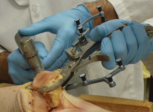
Figure 1. Resecting the patella with an oscillating saw after setting the orientation and placement of the computer-assisted sawguide. Note the “G” marker array mounted on the sawguide and the “Y” marker array mounted on the patella.

Figure 2. Real-time navigation screen for the computer-assisted technique. The current sawguide position and orientation (in red) are shown relative the resection goal (in black). Information is provided both visually and numerically. The SI view is relatively easy for the user to understand because the left/right rotations of the physical sawguide correspond to left/right rotations of the visual image. Since the ML view is along the leg, the mental mapping between the sawguide movements and the virtual representation is less obvious, and they were therefore represented in two different visual manners: in the center of the display, as the user moves the back of the sawguide up and down (thus changing the orientation in the ML plane), the red bar moves up and down accordingly; on the right is the schematic view. The blue circles show the orientation of the everted patella relative to the femur for the SI (left) and ML (right) views. The “G” marker array was mounted on the sawguide and the “Y” marker array was mounted on the patellar bone; both needed to be visible for the navigation to occur. “P” refers to the digitizing pointer used in earlier steps. The text at the bottom of the screen provides guidance to the user, although the users never needed this beyond the initial training.
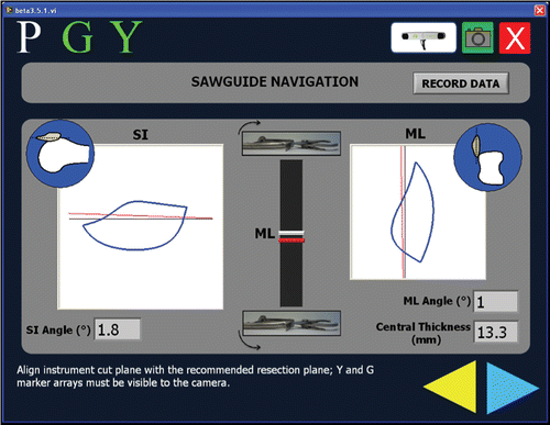
Figure 2. Real-time navigation screen for the computer-assisted technique. The current sawguide position and orientation (in red) are shown relative the resection goal (in black). Information is provided both visually and numerically. The SI view is relatively easy for the user to understand because the left/right rotations of the physical sawguide correspond to left/right rotations of the visual image. Since the ML view is along the leg, the mental mapping between the sawguide movements and the virtual representation is less obvious, and they were therefore represented in two different visual manners: in the center of the display, as the user moves the back of the sawguide up and down (thus changing the orientation in the ML plane), the red bar moves up and down accordingly; on the right is the schematic view. The blue circles show the orientation of the everted patella relative to the femur for the SI (left) and ML (right) views. The “G” marker array was mounted on the sawguide and the “Y” marker array was mounted on the patellar bone; both needed to be visible for the navigation to occur. “P” refers to the digitizing pointer used in earlier steps. The text at the bottom of the screen provides guidance to the user, although the users never needed this beyond the initial training.

Figure 3. Mediolateral (ML) resection angles achieved using the conventional and computer-assisted sawguide relative to the anterior surface of the patella, as determined from CT scans. The CAS technique was more repeatable than the conventional technique (p < 0.01). The CAS results are also given relative to the baseplate attached to the anterior surface, which was the basis for the navigation. Multiple cuts and caliper measurements were allowed for the conventional case; for the CAS case only a single cut was allowed. Positive angles indicate lateral under-resection or medial over-resection. Angles less than 7° are considered symmetric.
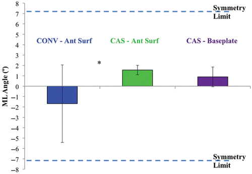
Figure 3. Mediolateral (ML) resection angles achieved using the conventional and computer-assisted sawguide relative to the anterior surface of the patella, as determined from CT scans. The CAS technique was more repeatable than the conventional technique (p < 0.01). The CAS results are also given relative to the baseplate attached to the anterior surface, which was the basis for the navigation. Multiple cuts and caliper measurements were allowed for the conventional case; for the CAS case only a single cut was allowed. Positive angles indicate lateral under-resection or medial over-resection. Angles less than 7° are considered symmetric.

Figure 4. Superoinferior (SI) resection angles achieved using the conventional and computer-assisted sawguide relative to the anterior surface of the patella, as determined from CT scans. Positive angles indicate inferior under-resection or superior over-resection. Angles less than 7° are considered symmetric. While both experimenters were highly accurate in their navigation, the baseplate tended to be tilted superoinferiorly for one experimenter, resulting in lower accuracy relative to the bone. There were no statistically significant differences between the CAS and conventional results.
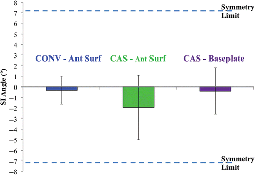
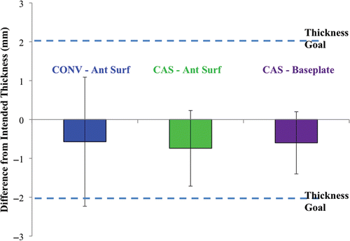
Figure 4. Superoinferior (SI) resection angles achieved using the conventional and computer-assisted sawguide relative to the anterior surface of the patella, as determined from CT scans. Positive angles indicate inferior under-resection or superior over-resection. Angles less than 7° are considered symmetric. While both experimenters were highly accurate in their navigation, the baseplate tended to be tilted superoinferiorly for one experimenter, resulting in lower accuracy relative to the bone. There were no statistically significant differences between the CAS and conventional results.

Figure 5. Difference from the intended central thickness for the conventional and CAS techniques, relative to the anterior surface and the baseplate. There were no statistically significant differences in the results.

Figure 5. Difference from the intended central thickness for the conventional and CAS techniques, relative to the anterior surface and the baseplate. There were no statistically significant differences in the results.

Reprints and Corporate Permissions

Please note: Selecting permissions does not provide access to the full text of the article, please see our help page How do I view content?

To request a reprint or corporate permissions for this article, please click on the relevant link below:

Academic Permissions

Please note: Selecting permissions does not provide access to the full text of the article, please see our help page How do I view content?

Obtain permissions instantly via Rightslink by clicking on the button below:

If you are unable to obtain permissions via Rightslink, please complete and submit this Permissions form. For more information, please visit our Permissions help page.