Figures & data
Figure 1. Measurement of femoral anteversion and the effect of condylar twist angle. (a) Measurement of femoral anteversion – angle between the condylar axis (green) and the femoral neck axis (red) [25]. (b) The condylar twist angle, caused by the posterior projection of the medial femoral condyle being greater than that of the lateral condyle, which externally rotates the transepicondylar axis of the femur [28].
![Figure 1. Measurement of femoral anteversion and the effect of condylar twist angle. (a) Measurement of femoral anteversion – angle between the condylar axis (green) and the femoral neck axis (red) [25]. (b) The condylar twist angle, caused by the posterior projection of the medial femoral condyle being greater than that of the lateral condyle, which externally rotates the transepicondylar axis of the femur [28].](/cms/asset/410084e8-92f2-4033-bf2c-ff2a21449024/icsu_a_690230_f0001_b.gif)
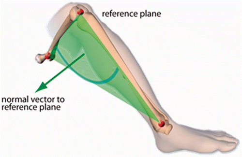
Figure 2. Ankle epicondyle piriformis (AEP) plane formed by the mid-point of the ankle malleoli, the mid-point of the femoral epicondyles, and the piriformis fossa. The normal vector to this plane is used instead of the condylar axis in imageless navigation to define the neutral rotation of the femur

Table I. Effect size.
Table II. CT method: Angle between the condylar axis and transepicondylar axis measured in the transverse plane (negative value = external rotation).
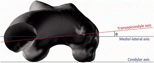
Figure 3. The angle between the medial-lateral and transepicondylar axes when viewed in the transverse plane.

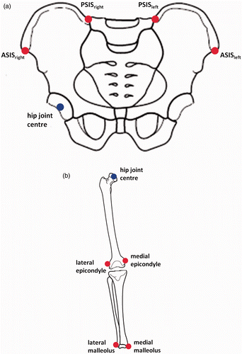
Figure 4. Gait analysis method marker positions. (a) Pelvic marker locations (in red). (b) Leg marker locations (in red).

Table III. Gait analysis method: Angle between the pelvic medial-lateral axis and the transepicondylar axis measured in the transverse plane (negative value = external rotation).
Table IV. Gait analysis method: Angle between the pelvic and femoral medial-lateral axes measured in the transverse plane.
