Figures & data
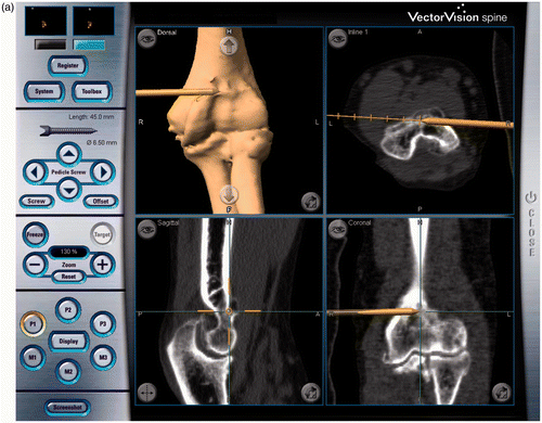
Figure 1. Registration and surface matching. (a) A reference array was placed on the medial side of the humerus. (b) A global registration was performed using 4 points, including the medial and lateral epicondyles and the two points on the edge of the olecranon fossa. Since the navigation software was designed for use in spinal surgery, the distal humerus was designated as vertebra L1, as shown in the screen shot. (c) Surface matching was then performed with 20 points on the posterior aspect of the distal humerus. The term “Accuracy: 1.0 mm” visible at the bottom of this screen was automatically displayed by the system.

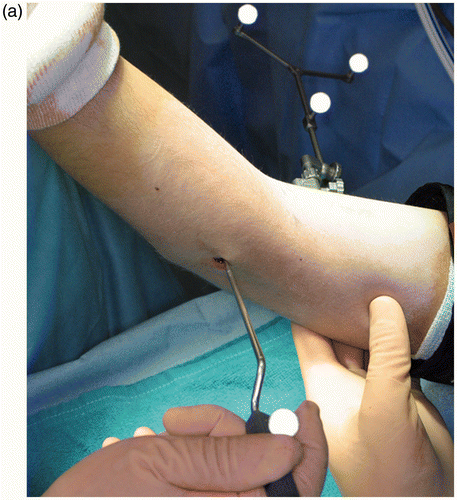
Figure 2. Navigation-assisted surgery. A drill burr with a mounted reference array is used for bone resection of the distal humerus. (a) Anterior side of the joint. The drill burr is shown as a gold rod that is drilling out the osteophyte on the coronoid fossa. (b) Posterior side of the joint. The drill is burring out the olecranon fossa.

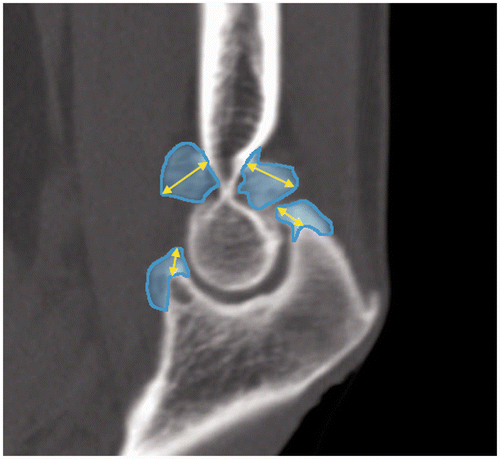
Figure 3. Measurement of bone morphology. A CT image of a sagittal plane through the bottoms of the coronoid and olecranon fossae of the distal humerus. The maximal values of the heights of the bone protruding from the contour surface, which is assumed to be the normal anatomical morphology, are shown. The heights of the bones (yellow lines with arrows) and their areas (in blue) are measured.

Table I. Patient data. Values are expressed as mean ± standard deviation with the range in parentheses.
Table II. Morphometric measurement of osteophytes. Values are expressed as mean ± standard deviation (range in parentheses). The height and area of the osteophyte and the reduction ratio of the osteophyte area were compared pre- and postoperatively.

