Figures & data
Figure 1. Three surface representations of cadaveric femurs demonstrating variability in Blumensaat's line (red) when viewed as sagittal sections looking towards the medial wall of the lateral femoral condyle.
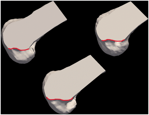
Figure 2. The standardized orientations of the femur and tibia. For the femur, the Z-axis is aligned with the femoral diaphysis (A) and the X-axis is defined by a line that allows the medial and lateral condyles to be aligned as in a perfect lateral 2D radiograph (B). (The figure demonstrates a femur with modified transparency to allow visualization of the overlap.) For the tibia, the X-axis is aligned with the medial-lateral slope of the tibial plateau (C) and the Z-axis is aligned such that the posterior-most aspects of the medial and lateral condyles of the tibial plateau are linearly aligned (D).
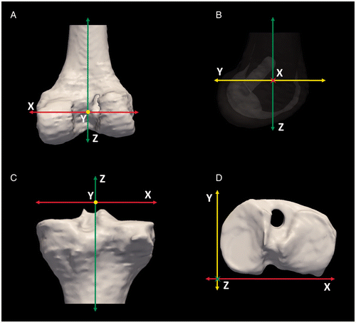
Figure 3. A cylinder with a diameter of 10 mm was used to simulate the drill bit used to create the ACL tunnels. The cylinders were manually aligned with the tunnels of the femur (A) and tibia (B).
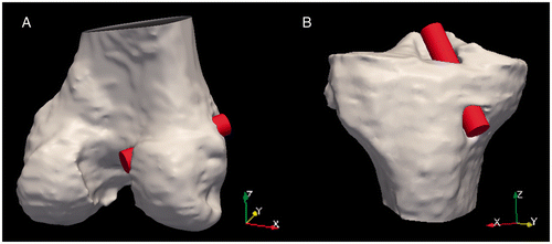
Figure 4. Tibial tunnel angles (α, β, γ) were measured based on the tunnel centerline's deviation from the surgically oriented coordinate system (A), as demonstrated looking down the Y-axis (B) and the X-axis (C). The points used to calculate the angles are labeled as p1 and p2.
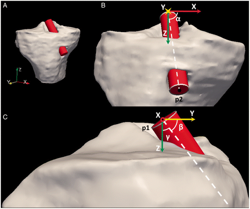
Figure 5. Femoral tunnel angles (α, β, γ) were measured based on the tunnel centerline's deviation from the surgically oriented coordinate system (A), as demonstrated looking down the Y-axis (B) and the X-axis (C). The points used to calculate the angles are labeled as p1 and p2.
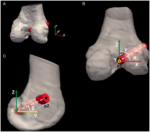
Figure 6. The virtual drill bits were cropped to match the tunnel aperture on the femur and tibia. Several views are provided, including the posterior aspect of the distal femur (A), a sagittal view of just the lateral femoral condyle (B), and the tibia (C).
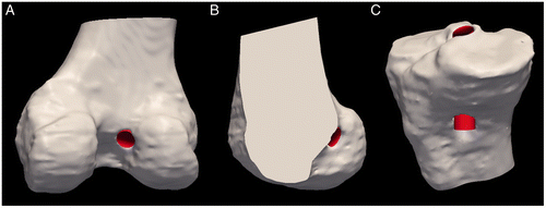
Figure 7. (A) Measurement (a/A) of the tunnel aperture centerpoint based on the anterior-posterior distance of the tibial plateau. (B) Measurement (m/M) of the tunnel aperture centerpoint based on the medial-lateral distance of the tibial plateau.
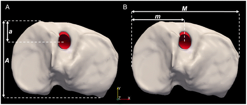
Figure 8. (A) Measurement (c/C) of the tunnel aperture centerpoint based on the diameter of the lateral femoral condyle. (B) Measurement (n/N) of the tunnel aperture centerpoint based on the height of the intercondylar notch.
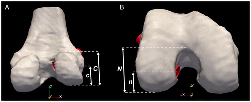
Figure 9. (A) A digital phantom including nine virtual drill bits used to test the angular measurements. (B) A second digital phantom including three virtual drill bits encased in a cube, used to test the aperture localization measurements.
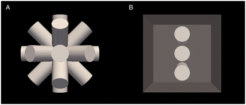
Table I. Intracorrelation coefficient for 4 trained users for each measurement.