773
Views
7
CrossRef citations to date
0
Altmetric
Research Article

Sensor fusion for laparoscopic surgery skill acquisition

, , &
Pages 269-283 | Received 15 Nov 2011, Accepted 13 Aug 2012, Published online: 25 Oct 2012

Figures & data

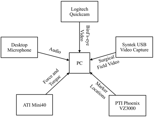
Figure 1. Overview of system components.

Figure 1. Overview of system components.

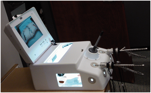
Figure 2. Endo-trainer from 3D-Med used in the studies.

Figure 2. Endo-trainer from 3D-Med used in the studies.

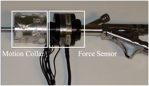
Figure 3. Aluminum collar with markers and force sensor mounted on needle driver.

Figure 3. Aluminum collar with markers and force sensor mounted on needle driver.

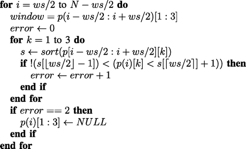
Figure 4. Median discard filter

Figure 4. Median discard filter

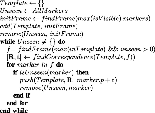
Figure 5. Template construction algorithm.

Figure 5. Template construction algorithm.

Figure 6. Needle driver, string, and weight used during the calibration procedure to align the template and force coordinate systems. Orange ellipses indicate the location of optical markers.
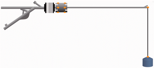
Figure 6. Needle driver, string, and weight used during the calibration procedure to align the template and force coordinate systems. Orange ellipses indicate the location of optical markers.

Figure 7. Sample trajectory recorded from the system, with instrument orientation axes overlaid at constant time intervals. The black line represents the 3D trajectory taken by the instrument, while the red, green and blue lines (terminated by an ×, triangle and star, respectively) represent the local x, y, and z axes of the instrument.
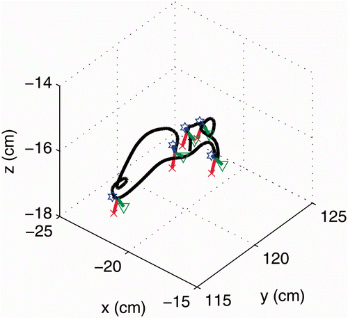
Figure 7. Sample trajectory recorded from the system, with instrument orientation axes overlaid at constant time intervals. The black line represents the 3D trajectory taken by the instrument, while the red, green and blue lines (terminated by an ×, triangle and star, respectively) represent the local x, y, and z axes of the instrument.

Figure 8. Sampled position, force, and resulting work signal from a random segment of a recorded procedure.
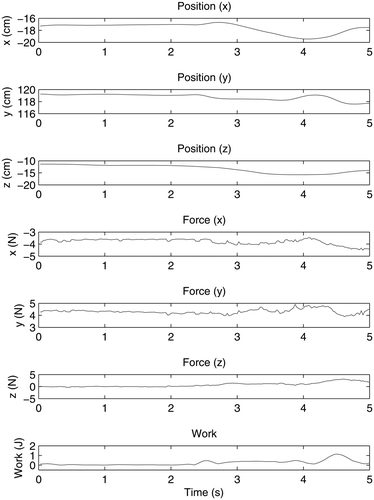
Figure 8. Sampled position, force, and resulting work signal from a random segment of a recorded procedure.

Figure 9. View from the laparoscopic camera for (a) the FLS pegboard task and (b) the simple interrupted suturing task.

Figure 9. View from the laparoscopic camera for (a) the FLS pegboard task and (b) the simple interrupted suturing task.

Table I.  Significance of correlations between each measure and each task. (1: fundamental laparoscopic skills; 2: simple interrupted suture; 3: continuous running suture) for non-dominant (N) and dominant hand (D). * indicates significant correlation (p < 0.05); – indicates non-significant or no correlation.
Reprints and Corporate Permissions

Please note: Selecting permissions does not provide access to the full text of the article, please see our help page How do I view content?

To request a reprint or corporate permissions for this article, please click on the relevant link below:

Academic Permissions

Please note: Selecting permissions does not provide access to the full text of the article, please see our help page How do I view content?

Obtain permissions instantly via Rightslink by clicking on the button below:

If you are unable to obtain permissions via Rightslink, please complete and submit this Permissions form. For more information, please visit our Permissions help page.