Figures & data
Figure 1. Radiographs of the first broken-nail removal by a modification of the technique of Magu et al. Citation[2]. (a) Lateral view of the femoral pseudarthrosis with the broken nail. (b) Intraoperative fluoroscopic image showing an antegrade inserted guide-wire, which was bent outside the knee after distal perforation. (c) Retraction of the bent guide-wire removes the distal part of the broken nail.
![Figure 1. Radiographs of the first broken-nail removal by a modification of the technique of Magu et al. Citation[2]. (a) Lateral view of the femoral pseudarthrosis with the broken nail. (b) Intraoperative fluoroscopic image showing an antegrade inserted guide-wire, which was bent outside the knee after distal perforation. (c) Retraction of the bent guide-wire removes the distal part of the broken nail.](/cms/asset/81c8c034-5877-48ae-8af4-d74dbd440d4e/icsu_a_741623_f0001_b.gif)
Figure 2. Radiographs of the navigated nail removal. (a, b) Healed femoral pseudarthrosis after re-nailing; deep placement of the nail in the medullar cavity (18 mm) made the implant removal demanding. (c, d) Postoperative X-ray control showing complete nail removal via less invasive incisions (red circles).
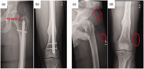
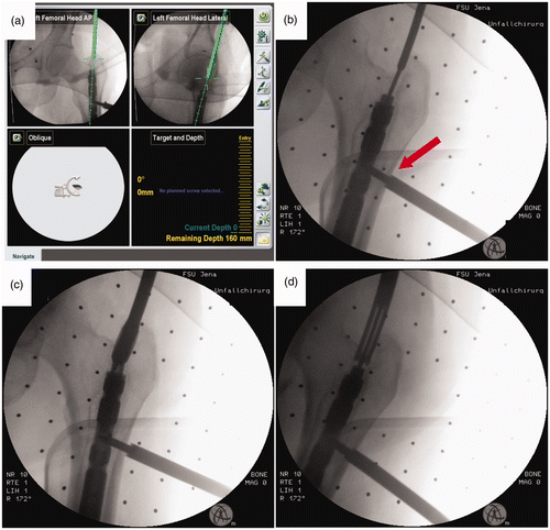
Figure 3. Navigated technique for minimally invasive removal of buried nails. (a) Screenshot of the navigation system display. Based on two orthogonal 2D fluoroscopic images (antero-posterior and axial) a navigated guide-wire can be placed precisely in the hole of the end-cap. (b) Intraoperative fluoroscopic control image showing the precise guide-wire placement via a navigated drill sleeve. The dynamic reference base for the navigation procedure was placed in an existing drill hole after removal the most proximal locking screw (red arrow). (c) Preparation of the osseous tunnel to the nail with a cannulated driller. (d) Removal of bone overgrowth around the end cap using a cannulated crown drill.