1,336
Views
53
CrossRef citations to date
0
Altmetric
Research Article

Computer-assisted planning and navigation improves cutting accuracy during simulated bone tumor surgery of the pelvis

, , , , &
Pages 19-26 | Received 24 May 2012, Accepted 14 Oct 2012, Published online: 26 Nov 2012

Figures & data

Figure 1. Bone cutting performed with an oscillating saw. The simulated bone is a polyurethane foam right hemipelvic model and is clamped by means of template supports and screw fixation. The reference block is a plastic POM-C resin block and is used to define the global reference frame R0.
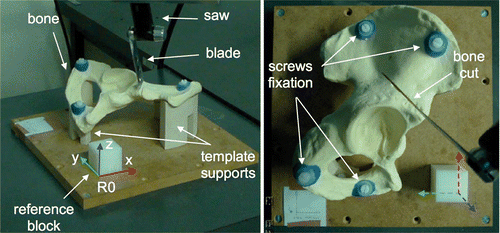
Figure 1. Bone cutting performed with an oscillating saw. The simulated bone is a polyurethane foam right hemipelvic model and is clamped by means of template supports and screw fixation. The reference block is a plastic POM-C resin block and is used to define the global reference frame R0.

Figure 2. Preoperative planning of tumor cutting on the 3D CT model of the hemipelvic bone. The tumor is simulated by a sphere centered on the acetabulum. The planning consists of four target planes defining the desired cutting of the simulated tumor, including a first plane in the ischium, a second plane in the pubis, and a third and fourth plane forming two angular cuts in the ilium. The plane coordinates are expressed in the reference frame R0.
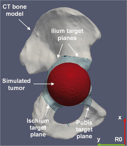
Figure 2. Preoperative planning of tumor cutting on the 3D CT model of the hemipelvic bone. The tumor is simulated by a sphere centered on the acetabulum. The planning consists of four target planes defining the desired cutting of the simulated tumor, including a first plane in the ischium, a second plane in the pubis, and a third and fourth plane forming two angular cuts in the ilium. The plane coordinates are expressed in the reference frame R0.

Figure 3. Navigated freehand cutting process within the pelvis. (A) While the oscillating saw is tracked in the operating room by an optical localizer, the real-time visual feedback consists of continuously refreshing both the position and orientation of the saw blade relative to the 3D CT model of the simulated bone. The target plane is represented by a red line. The blade is represented by a green rectangle delimited by a yellow line (the distal extremity of the blade) and a blue line (the proximal extremity of the blade). (B) The distal extremity of the blade is positioned on the bone surface on the target plane since the yellow line overlaps the red line. (C) The blade is correctly aligned on the target plane since the red, yellow and blue lines overlap perfectly.
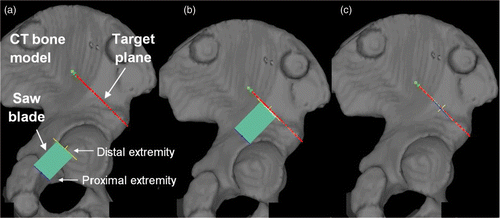
Figure 3. Navigated freehand cutting process within the pelvis. (A) While the oscillating saw is tracked in the operating room by an optical localizer, the real-time visual feedback consists of continuously refreshing both the position and orientation of the saw blade relative to the 3D CT model of the simulated bone. The target plane is represented by a red line. The blade is represented by a green rectangle delimited by a yellow line (the distal extremity of the blade) and a blue line (the proximal extremity of the blade). (B) The distal extremity of the blade is positioned on the bone surface on the target plane since the yellow line overlaps the red line. (C) The blade is correctly aligned on the target plane since the red, yellow and blue lines overlap perfectly.

Figure 4. Parameters for the geometrical and surgical evaluation of each cut plane of a tumor cutting. (A) Location (L) (mm) and surgical margin (SM) (mm); the target plane is the dashed line; the cut plane is the solid line. *The cut plane is represented here by a line instead of a curve for better clarity in the definition of L and SM. See main text for details. (B) Flatness (F) (mm); the cut plane is the solid curve.
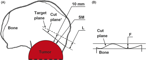
Figure 4. Parameters for the geometrical and surgical evaluation of each cut plane of a tumor cutting. (A) Location (L) (mm) and surgical margin (SM) (mm); the target plane is the dashed line; the cut plane is the solid line. *The cut plane is represented here by a line instead of a curve for better clarity in the definition of L and SM. See main text for details. (B) Flatness (F) (mm); the cut plane is the solid curve.

Reprints and Corporate Permissions

Please note: Selecting permissions does not provide access to the full text of the article, please see our help page How do I view content?

To request a reprint or corporate permissions for this article, please click on the relevant link below:

Academic Permissions

Please note: Selecting permissions does not provide access to the full text of the article, please see our help page How do I view content?

Obtain permissions instantly via Rightslink by clicking on the button below:

If you are unable to obtain permissions via Rightslink, please complete and submit this Permissions form. For more information, please visit our Permissions help page.