Figures & data
Figure 1. Snapshots taken during the performance of the LC operation on the LapVR simulator: (a) dissection of the gallbladder; (b) clipping/cutting of the cystic duct/artery; (c) liver bed coagulation; and (d) gallbladder removal.
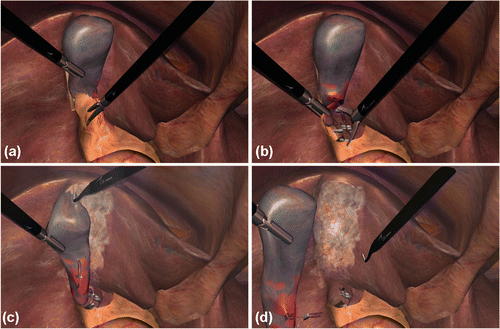
Figure 2. Schematic diagram of the surgical workflow segmentation algorithm. The algorithm starts by constructing the training set (top left) that contains the regression coefficients of each phase (weights; middle row). A candidate signal is then processed via GMMAR (bottom left) and the estimated mixture weights are compared to those of the training set so as to determine which phase it corresponds to. The signal is then segmented by taking into account the prior probabilities (wi) of each mixture weight (bottom right). The algorithmic steps are described in the inset.
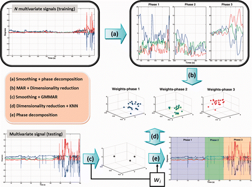
Figure 3. Model selection curves for the left and right hand.
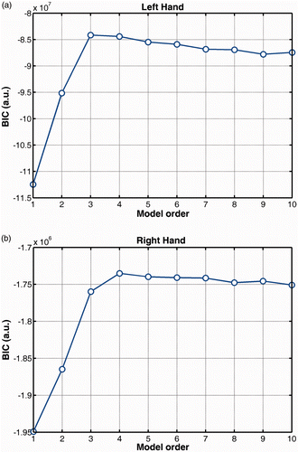
Figure 4. (a) Examples of raw and smoothed hand signals for the three rotation angles (roll, pitch, yaw: x, y, z). (b) Histograms of the residuals computed with MAR models for each phase hand signal.
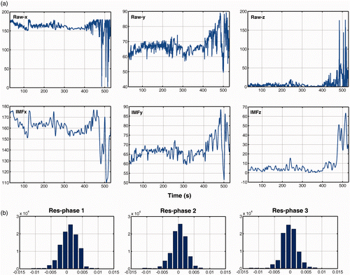
Figure 5. Examples of smoothed hand signals along with the posterior probabilities of each Gaussian mixture component (shown in different colors) for the left (a) and right (b) hand. Dashed lines denote the objective timings separating the surgical phases. The upper graphs in (a) and (b) are filled with different colors indicating the time course of the three surgical phases as determined by the algorithm.
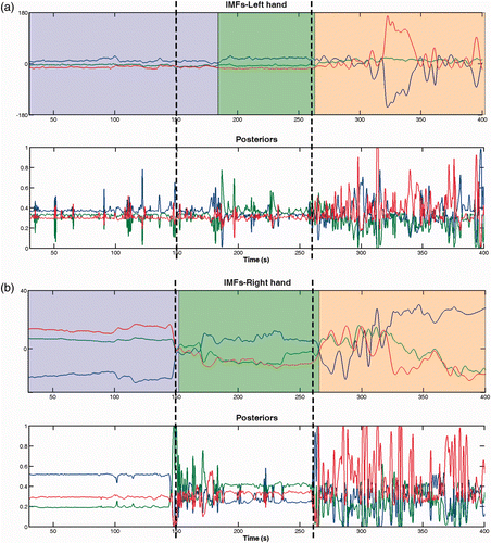
Table I. Precision (Pre) and recall (Rec) for each surgical phase (% average ± SD).
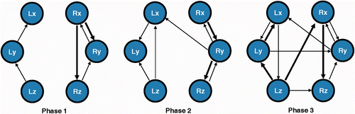
Figure 6. Hand motion networks. Arrows indicate significant signal connections (P < 0.05); increased weight denotes strong couplings (P < 0.01).