Figures & data
Figure 1. Preoperative X-ray of the affected foot. The MTP-1 joint is fused in malposition (yellow arrow). The X-ray shows the internal rotation of the proximal phalanx (white arrow), and the sesamoid bone is laterally shifted (blue arrow) (Hardy grade 4).
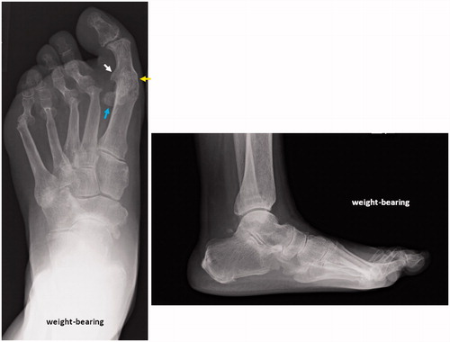
Figure 2. The affected foot. The laterally shifted tibial sesamoid and osseous rising of the proximal phalanx base have caused painful callosities (yellow arrows).
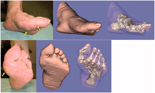
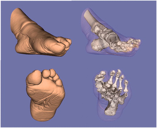
Figure 3. Three-dimensional evaluation of the affected foot. The severely pronated position of the proximal phalanx against the metatarsal (approximately 70° pronated) is evident.
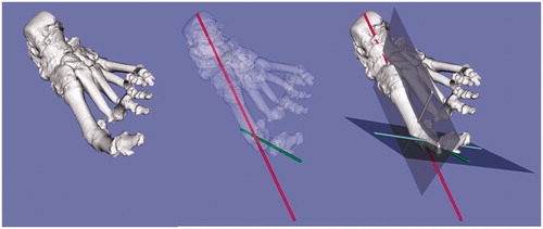
Figure 4. The simulation for setting the metatarsal and proximal phalanx cutting templates (red). The K-wires (green) are perpendicular to the longitudinal axis of the metatarsal and proximal phalanx. The projections given were programmed to guide the bone saw in cutting the metatarsal and phalanx perpendicular to the longitudinal axis (*).
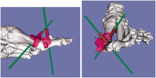
Figure 5. Intraoperative photograph of the custom-made surgical guide fixed with K-wires. (A, B) The distal end of the metatarsal and the proximal end of the proximal phalanx are fixed with K-wires with the aid of the 3D-CT-based custom-made surgical guide designed preoperatively. (C) The rotational position between the two bones is adjusted using the fixed K-wires as a rotational guide.
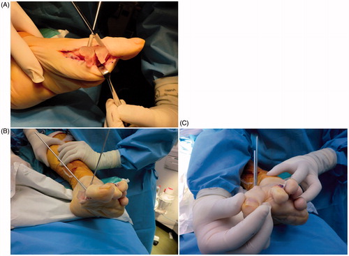
Figure 6. Postoperative X-ray of the affected foot. The MTP-1 joint is re-fused in the proper rotational position. Improvements in the pronated deformity and the sesamoid position are seen (Hardy grade 2).
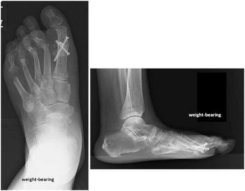
Figure 7. Images created from the 3D-CT data of the affected foot postoperatively. The rotational deformity is corrected, and the sesamoid is properly repositioned postoperatively.