Figures & data
Figure 1. (a) During the draping the patient's forehead and eyes are exposed, and eyebrows are covered with sterile gauze to protect them from adhesive surgical film. (b) Exposed forehead is covered by transparent surgical film. (c) Mount reference frame on the forehead and fix it firmly with fragmented surgical film.
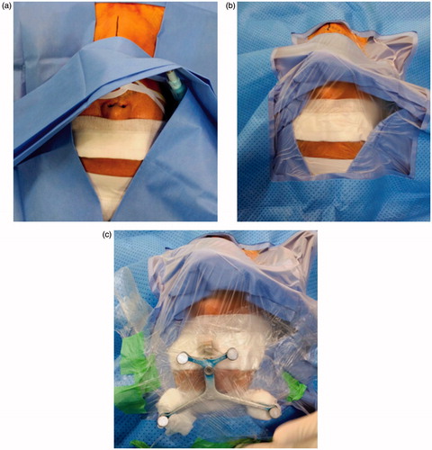
Figure 2. A custom-made metal sleeve (top of picture) can maintain a constant connection between the tip of the caspar pin (bottom right of picture) and the navigation probe (bottom left of picture), none of which were taken handheld. Each tip of caspar pin and navigation probe contacts promptly by the metal sleeve.
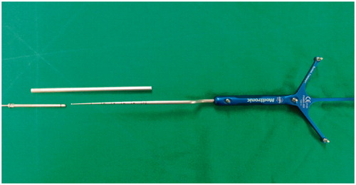
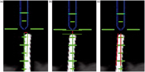
Figure 3. (a) A red bidirectional arrow indicates horizontal distance in sagittal plane between center of navigation probe (top) and caspar pin (bottom). (b) A red bidirectional arrow indicates vertical distance in sagittal plane between each end of navigation probe (top) and caspar pin (bottom). (c) Two red lines indicate cobb’s angle in sagittal plane between navigation probe (top) and caspar pin (bottom).