Figures & data
Figure 1. RPs and coordinate systems for pelvic and femoral bone. RASI and LASI, right and left anterior iliac spines; RPT and LPT, right and left pubic tubercles; RIS and LIS, right and left distal-most points of the ischium; PUB, midpoint of the pubic symphysis; SACR, sacral midpoint for the pelvic frame; FH, center of the femoral head; FOS, pyriform fossa; PF, posterior-most point of the proximal femur; MFC and LFC, medial and lateral posterior condyles; KC, knee center for the femoral frame.
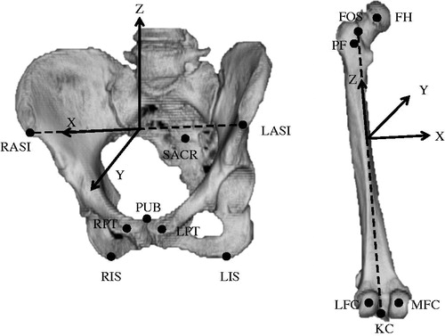
Figure 2. Manual methods for constructing a bony coordinate system on postoperative CT images. These examples are for a pelvic coordinate system. For the first manual method (M1), postoperative RPs, or RPsM1, were chosen at the prescribed position without a specific tool in one planning module. The pelvic coordinate system constructed using RPsM1 was defined by an affine matrix (Xpm1) in the coordinate system of postoperative CT images. For the second manual method (M2), postoperative RPs (RPsM2) were chosen at a position with as little deviation as possible from preoperative RPs by checking preoperative RPs on another monitor. The pelvic coordinate system constructed using RPsM2 was defined by an affine matrix (Xpm2) in the coordinate system of postoperative CT images.
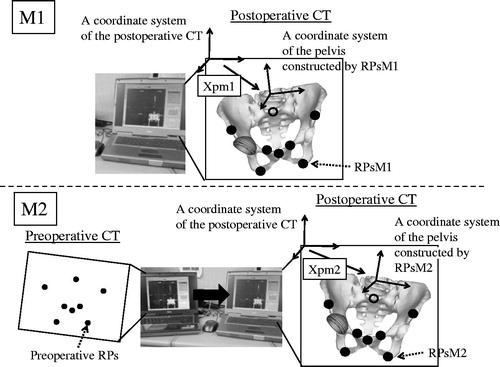
Figure 3. A computer matching method used as a gold standard for constructing a bony coordinate system on postoperative CT images. These examples are for a pelvic coordinate system. The pelvic model on the preoperative CT image was overlaid exactly on the postoperative CT image using the volume registration method. The rotation and translation of the preoperative CT coordinate system during this matching process was recorded as an affine matrix (Tp). The preoperative RPs on the preoperative image were converted on the postoperative image as RPsVR (reference points for the computer matching method), maintaining the preoperative special relationship to the pelvis by calculating the Tp. The pelvic coordinate system that was constructed using the RPsVR was defined by an affine matrix (Xpvr) in the coordinate system of the postoperative CT image.
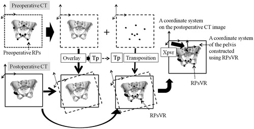
Figure 4. A simulation to study the influence of discrepancies between postoperative coordinate systems for the pelvis and femur created using the computer matching method (VR) and those constructed using the first or second manual methods (M1 or M2) on postoperative evaluation of implant orientations. These examples are for a cup simulation. Here, a virtual cup has been set at 40°of radiographic inclination and 15° of radiographic anteversion to the postoperative pelvic coordinate system constructed by VR, which defined matrix Xpvr in the coordinate system for the postoperative CT image. We calculated cup orientation when the virtual cup was viewed from the postoperative pelvic coordinate system constructed by M1 or M2, which defined matrix Xpm1 or Xpm2, respectively.
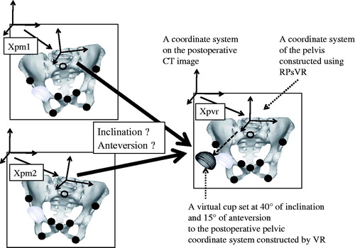
Table 1. Deviation of RPsM1 and RPsM2 from RPsVR.
Table 2. The influence of construction method for the postoperative bony coordinate system on cup and stem orientation.
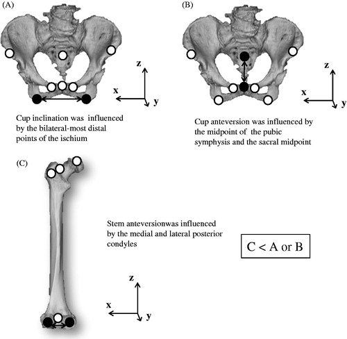
Figure 5. RPs that can theoretically influence (A) cup inclination, (B) cup anteversion, and (C) stem anteversion (black circles).