Figures & data
Figure 1. The reconstructed distal femur just before implantation of the stemmed femoral component. A. Synthetic distal femur in upside-down position. B. Reconstructed condyle with IBG. C. Femoral component with a thin cement layer. D. Connector with tantalum pellets glued at the flange for RSA measurements. E. Tantalum pellet inserted at the femoral shaft.
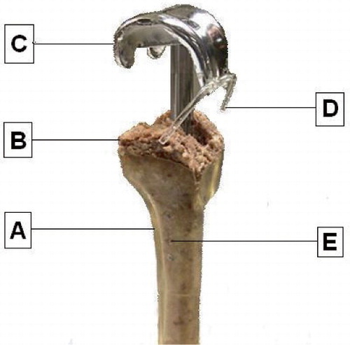
Figure 2. The sliding stem mechanism. A. Inner screw to lock or initiate the sliding mechanism. B. Hexagonal screw to connect the stem to the intercondylar box of the femoral component. C. Sliding part of the stem. D. Cylindrical protector, keeping the bone graft out of the sliding mechanism. E. Fluted stem with inner diameter of 10 mm and outer diameter of 12 mm.
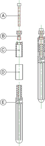
Figure 3. Schematic representation of tests A, B, and C. The distal femur is marked as “A”, the impacted bone graft as “B”, the femoral component as “C”, and the sliding stem connection as “D”. During test A, the femoral component was extended with a rigidly connected stem. Before test B, the inner screw was removed to initiate the sliding stem mechanism. To disconnect the stem from the femoral component, the hexagonal screw was removed before test C.
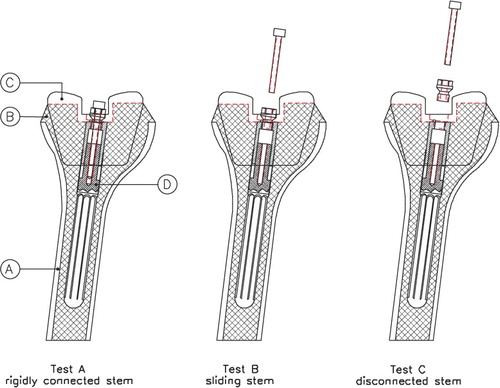
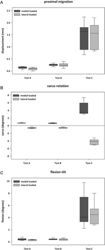
Figure 4. Box plots with medians and interquartile ranges of the proximal migration (panel A), varus rotation (panel B), and flexion tilt (panel C) of the femoral component after 30 minutes of loading during tests A, B, and C.
P-values of the differences in proximal migration, varus rotation, and flexion tilt during medially and laterally loaded situations after 30 minutes of alternating axial loading