Figures & data
Figure 1. Stem antetorsion measurement. The mechanical axis was defined by 2 points: the center of the femoral head and the center of the caudal contact points of the femoral condyles. “Antetorsion plane” was defined by a third point on the prosthesis representing the direction of the neck. A caudal condylar plane was created orthogonal to the mechanical axis. The angle between the condylar axis projected on this plane and the normal to the “antetorsion plane” subtracted by 90° gave the torsion angle.
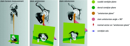
Figure 2. Range of stem torsion in 60 hips.
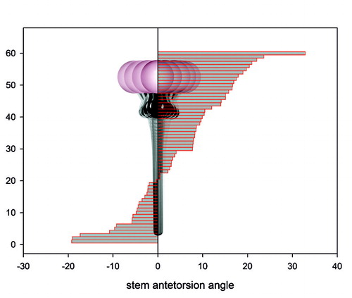
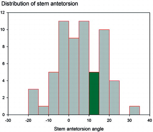
Figure 3. Distribution of stem torsion in 60 hips. The 10–15° of antetorsion shown in green is considered to be the normal stem antetorsion.
Femoral antetorsion measurements