Figures & data
Figure 1. Schematic pictures showing the methods for radiographic assessment of mechanical axis (A), tibiofemoral angle (B), and femoral angle (C).
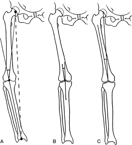
Figure 2. Bland-Altman plots showing differences from mean for mechanical axis measurements in 52 legs, comparing true-size films to short films (A), radiological workstation (B), and PC (C).
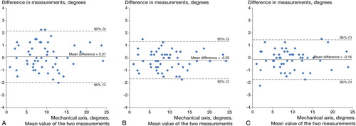
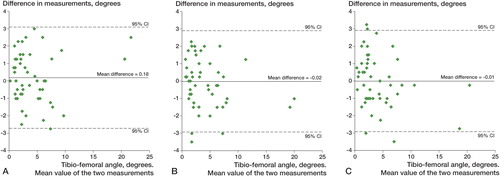
Figure 3. Bland-Altman plots showing differences from mean for tibio-femoral angle measurements in 52 legs, comparing true-size films to short films (A), radiological workstation (B), and PC (C).