
Figures & data
Figure 1. The Episeal articular resurfacing implant.
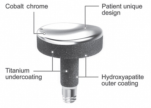
Figure 2. Blown-up schematic illustration of the markers measured on the implant. The distal part of the component was machined into a 3.0-mm hemisphere. A 1.0-mm tantalum marker (black solid circle) was glued to this hemisphere. The markers measured (red crosses) were: (1) manual measurement of the center (dotted circle) of the 3.0-mm hemisphere (hemisphere RSA); (2) manual measurement of the distal tip of the implant (tip RSA); and (3) semi-automated measurement of the tantalum marker (standard RSA). The radiograph shows actual measurements of tip RSA (marker 131) and hemisphere RSA (marker 121) in a patient.
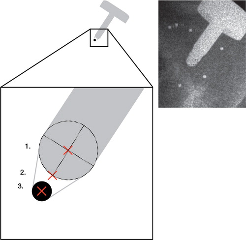
Table 1. Precision of standard, tip, and hemisphere RSA
Table 2. Accuracy of tip and hemisphere RSA