
Figures & data
Figure 1. Sequelae after distal radius fracture.
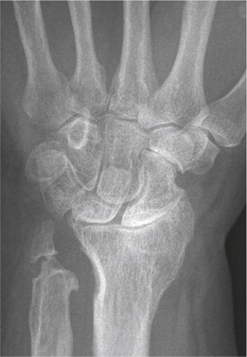
Figure 2. Radiograph of S-L ligament injury, with secondary degenerative changes, SNAC 3. Radioscaphoid and midcarpal arthrosis.
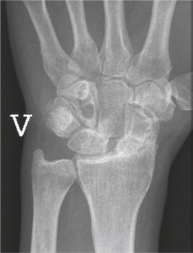
Figure 3. Frontal radiograph demonstrating lunate malacia. The lunate is fractured and fragmented, and the carpal height reduced.
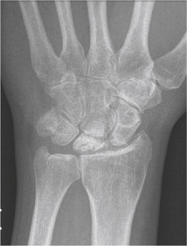
Figure 4. Scaphoid fracture operated with a screw. Non-union and misplaced screw causing destruction the radio-scaphoid joint.
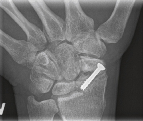
Figure 5. Four-corner fusion after SNAC 3 arthrosis. Follow-up frontal radiograph after 3 years.
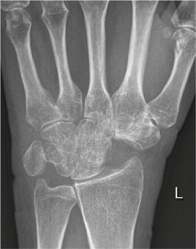
Figure 6. Proximal row carpectomy. Follow-up after 2 years.
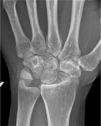
Figure 7. A) Wrist arthrodesis using plate fixation. B) Wrist arthrodesis with the Mannerfelt method.
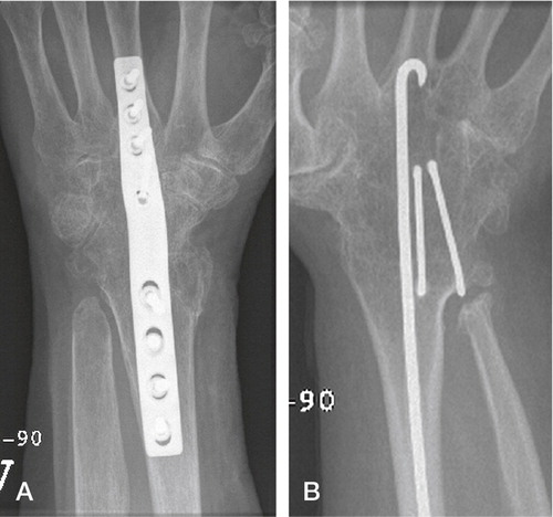
Figure 8. The Swanson wrist replacement with metal grommets. (Courtesy of Wright Medical Technology.)
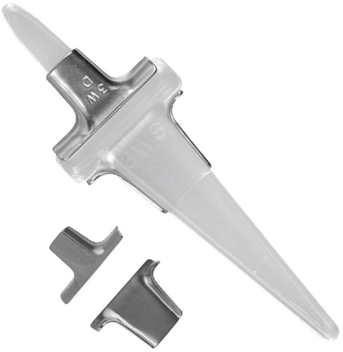
Figure 9. A) The first Volz arthroplasty with two distal prongs, and B) the modified Volz wrist arthroplasty with one central distal prong. (Courtesy of Dr Hamas.)
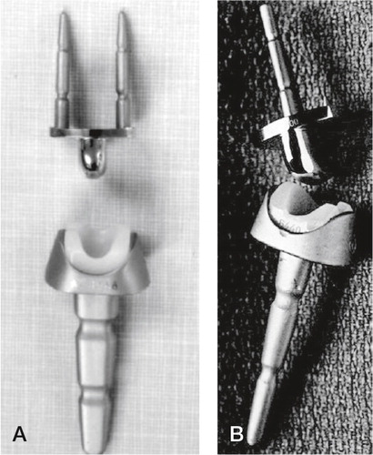
Figure 10. A) The Meuli I (polyester head), B) Meuli II (polyethylene head) and C) The Meuli III, metal-on-UHMWPE articulation. (Courtesy of Dr Mraz.)
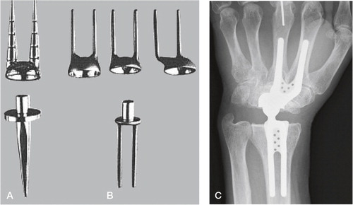
Figure 11. The Trispherical wrist arthroplasty. (Courtesy of Dr Figgie.)
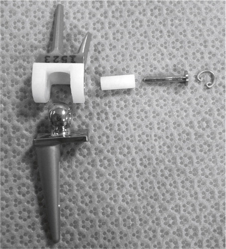
Figure 12. A) The Guepar wrist arthroplasty with microscrew. B) Radiologically loose distal and proximal components. (Courtesy of Dr Hubach.)
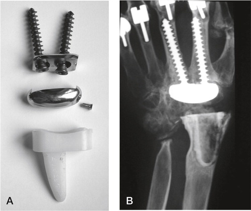
Figure 13. The Biax arthroplasty. (Courtesy of Dr Osnes-Ringen)
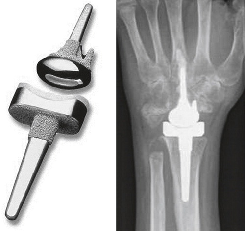
Figure 14. Sandblasted and porous coated steel proximal and distal components, UHMWPE radial cup, proximal steel carpal ball, condylar UHMWPE cylinder and distal steel component. (Courtesy of Dr Levadoux.)
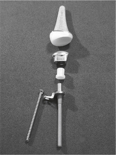
Figure 15. The APH wrist. (From Radmer et al., Journal of Hand Surgery, 1999, Reprint permission from Rightslink.)
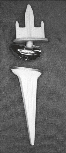
Figure 16. The development of the Universal arthroplasty system. A) Menon’s first edition. (From J Menon, Journal of Arthroplasty 1998, reprint permission from Rightslink). B) The second edition (Universal) with the central peg with indentations. C) The contemporary Universal 2. B) and C) Courtesy of Dr van Winterswijk.
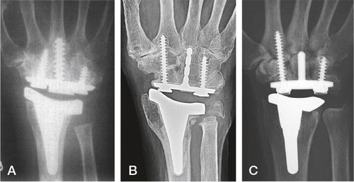
Figure 17. The total modular wrist system (TMW). A) The constrained version (upper), the unconstrained version (lower). B) Implant in situ. (Courtesy of Dr Hubach and OrthoCube.)
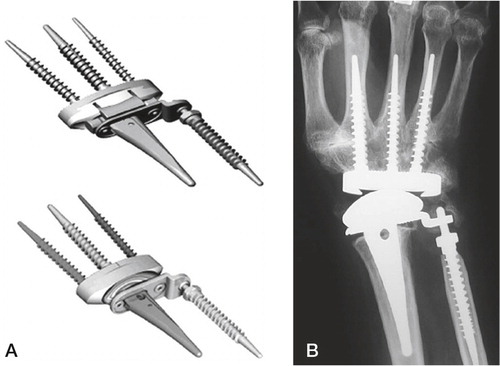
Figure 18. The Maestro wrist arthroplasty, Biomet.
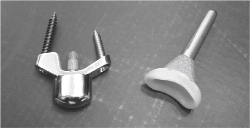
Figure 19. The Remotion wrist arthroplasty.
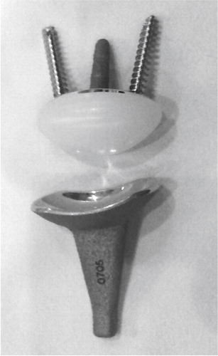
Figure 20. The screwshaped implants used in the second paper. A) HA coating (whitish). B) Bonit®-coated.
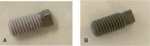
Figure 21. Peroperative view. A) The femur screw is placed. B) Prior to closure. Three screws in situ placed in the knee region, one in the distal condylar femur region and two in the proximal tibia.
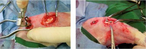
Figure 22. Illustration of the histomorphometric evaluation. A) Screw in situ in the cortical region of the rabbit tibia. B) Bone-implant contact. C) Bone area within the threads. D) Outfolded mirror image.
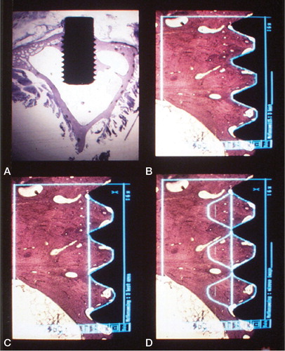
Figure 23. Histological section at 400 x magnification of a test sample demonstrating histomorphometric measurements at higher magnification within one thread. Implant in black. Direct bone-implant contact in red (% of length between the threads), yellow line demarcates bone-area within the thread minus green areas (% of area).
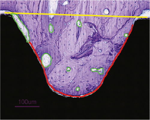
Figure 24. The arthroplasty used in the first two patients.
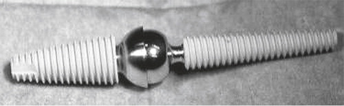
Figure 25. The instruments developed for implantation. From the top, cannulated radius reamer and distal reamer, implant screwdriver, countersinker for the socket, impactor for the ball and socket, pins for the cannulated system and trial components for final implant selection.
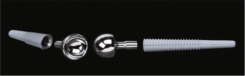
Figure 26. The Motec total wrist arthroplasty. Thicker and shorter proximal screw, thinner and longer distal screw. Courtesy of Swemac Orthopaedics AB, Linköping, Sweden.
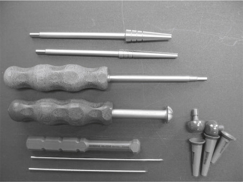
Figure 27. The instrument set for the arthroplasty surgery. Reamers with lower cutting threads, blunt guidewires, quick lock screwdriver and trials for tension and stability adjustment.
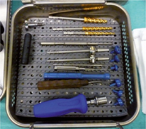
Table 1. Patient characteristics
Figure 28. A) The K-wire is drilled centrally through the capitate and into the third metacarpal. B) Reaming of the screw canal. C) Screwing home the distal component. D) Drilling the K-wire centrally into the radius. E) Reaming of the canal. F) The radius screw is in place and the socket has been punched into the screw. The ball is locked into the distal screw.
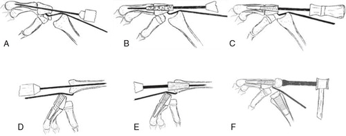
Figure 29. A) The uncoated SEM surface, demonstrating a more homogenous, less rough surface. B) The Bonit®-coated SEM surface demonstrating a spiky and relatively rough surface. C) The SEM surface on the HA-coated screw.
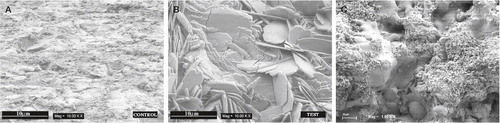
Figure 30. Histological picture of unused A) Bonit® screw revealing a continuous thin coating layer with black particles embedded and B) HA screw with the coating mainly on two thirds of the threads.
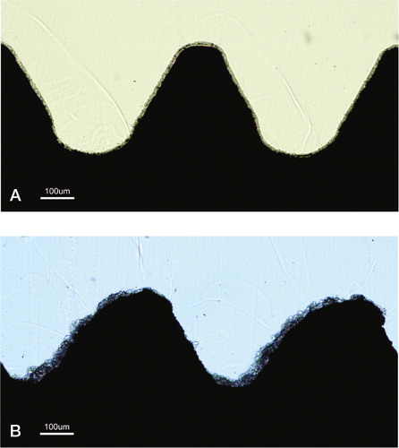
Table 2. Interferometric surface roughness analyses from study 1. Mean (SD)
Table 3. Interferometric surface roughness analysis from study 2. Mean (SD)
Table 4. The removal torque results in Ncm (SD) [range]
Table 5. The removal torque results in Ncm (SD)
Table 6. Bone length in mm. Mean (SD)
Table 7. Shear strength values in N/mm2. Mean (SD)
Table 8. Bone–implant contact (%). Mean (SD) [range]
Table 9. Bone area (%). Mean (SD) [range]
Figure 31. Photomicrographs of sections. a) Six-week Bonit® screw, bulk staining with basic fuchsine. b) Overview of a 52-week sample demonstrating the shape and position of the screw and the macroscopic appearance in the tibial bone. c) Magnification of a 52-week Bonit® screw demonstrating the bone-implant contact. Toluidine blue routine histological staining in b) and c).
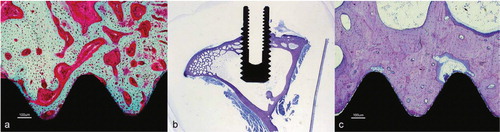
Figure 32. Close up of a Bonit®-coated screw at 12 weeks. The entire interface region reveals remodelled bone (RB) tissue. Except macrophages being observed in the soft tissue regions in the interface no inflammatory reactions were observed. Cement lines (CL) are clearly visible between new formed bone and old cortical bone (OB). Both bone forming and bone resorption cavities can be observed. Toluidine blue routine histological staining.

Figure 33. Photomicrographs of HA-coated implants: a) 6-week bulk staining with basic fuchsine. b) Overview of the 52-week sample demonstrating the shape and position of the screw and the macroscopic appearance. c) Magnification of the 52-week HA screw. Toluidine blue routine histological staining in b) and c).
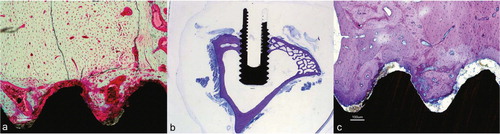
Figure 34. A 12-week close up of a HA-coated implant demonstrating loose HA particles (arrows) in the soft tissue outside thread peak as well as in bone remodelling cavities further away from the implant. Older cortical bone (OB) can be observed separated from younger bone by cement lines (CL). Note regions of more woven bone (WB) (immature) structure internalized in the remodelled bone. Toluidine blue routine histological staining.
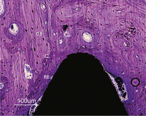
Figure 35. Patient 1 (first edition prosthesis). A) after 1 year, intimate bone-implant contact in the radius and capitate, radiolucent line surrounding the metacarpal part, B) after 2.5 years, a loose distal component with distal screw migration, C) arthrodesis, asymptomatic open CMC 3 joint, D) 3 years after rearticulation, intimate bone-implant contact and CMC 3 arthrodesis after bone transplantation. The DRUJ is unaffected.
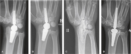
Figure 36. Patient 7 (second edition). A) postoperative image showing near perforation of the dorsal cortex of the radius, B) 1 year postoperatively demonstrating intimate bone-implant contact along both components, traces of bone radially and ulnarly C) At 6 years, ectopic bone has rebuilt the radial styloid after resection, spots of mature bone are seen in the soft tissue ulnarly. The DRUJ is unaffected.
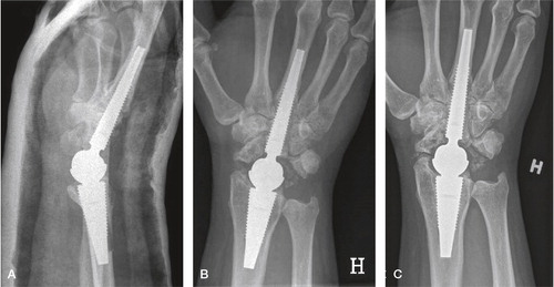
Table 10. Radiological results
Table 11. Patient satisfaction at follow-up
Table 12. Range of motion (°) and grip strength (kg)
Figure 37. A) Preoperative SLAC wrist, B) Frontal 3 years follow-up C) Lateral projection at 3 years follow-up. Intimate bone-implant contact without lines or osteolysis.
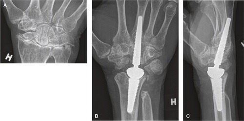
Figure 38. A) At 4 years, well integrated arthroplasty and well-functioning wrist. B) At 5.5 years, loosening of both components with enveloping double lines, subsidence and compensatory metacarpal diaphyseal widening.
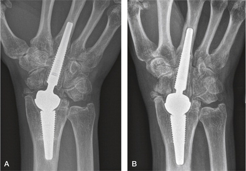
Figure 39. Focal periarticular radial osteolysis filling out the radial styloid at 3 years. Sclerotic line limiting the non-progressing lesion. Excellent clinical outcome.
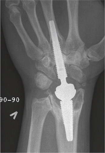
Figure 40. At 5 years, periprosthetic capitate lines without progression. Still intimate bone-implant contact in the metacarpal and radius.
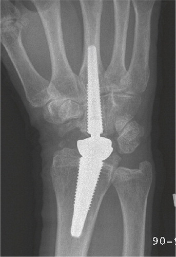
Figure 41. At 3 years, periprosthetic metacarpal lines without progression. Intimate bone-implant contact in the capitate and radius.
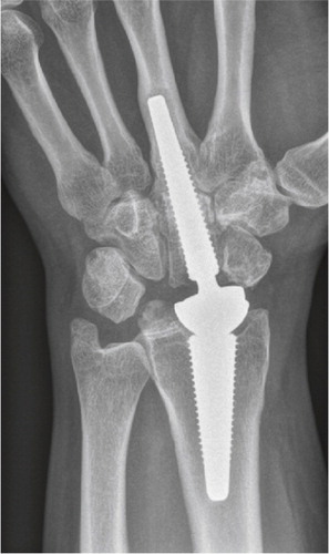
Figure 42. Kaplan-Meyer implant survival plot.
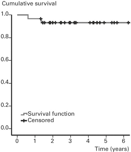
Table 13. The clinical result. Mean (SD)
Table 14. Working status