Figures & data
Figure 1. A. The 3 revised stems (left to right: case 1, case 2, and case 3). The bone attached to the implants is an indication of the ingrowth of the implants and the extent of bone defect caused during revision. B. Post-fracture radiograph of case 1. C. Pre-fracture radiograph of case 1. Cup angles were measured using image analysis software available at www.imatri.com (Joubert Citation2013).
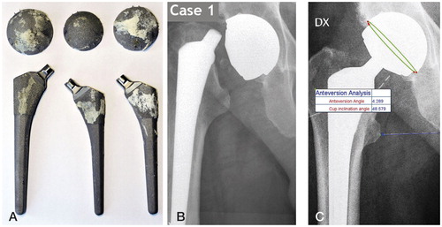
Table. Patient-, implant-, and surgery-specific data
Figure 2. The cut ball head insert and stem taper (with broken-off piece placed in original position) together with a new stem taper. The screw hole was drilled into the ball head insert for removal (which was unsuccessful); reaming of the slope of the insert allowed holding on to the insert and successful removal. The distal edge of the ball head insert is imprinted circumferentially onto the stem taper (arrow). The proximal edge of the contact between male and female taper and also the edge of the corroded area are marked on the taper insert together with the corresponding position on the stem taper. The insert shows the scratches in the non-corroded area originating from entrapped bone pieces (small arrows) in the broken-off stem taper piece.
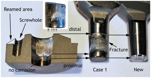
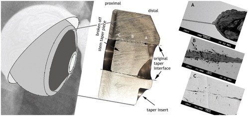
Figure 3. Upper panel: Stem fracture surface with fatigue cracks radiating out from the origin of the crack (black arrows) as a series of concentric rings (rest lines; left to right: cases 1 to 3). Case 3 had 3 crack origins, which subsequently coalesced into a unified fracture. Lower panel: All the fractures occurred slightly inside the female taper (about 1–4 mm proximally from the open end). The broken-off male stem taper piece remained inside the female ball head insert taper.
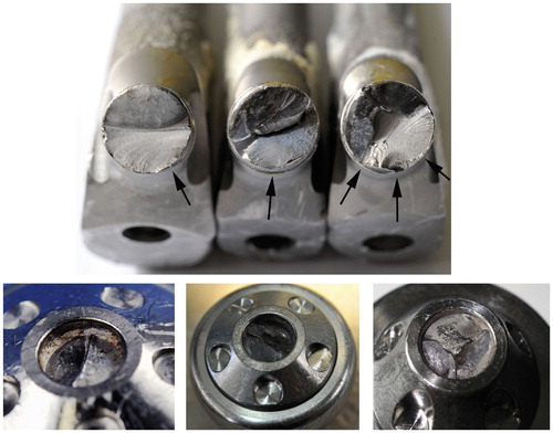
Figure 4. Left panel: Orientation of cup and head in case 2. Middle panel: Aligned orientation of the cut ball head insert with the fractured stem taper piece (dashed lines: original taper surface; areas A, B, and C for SEM are highlighted). Right panel: A. SEM of the corrosion cavity at the location of conversion to a smaller gap. B. SEM image of the middle of the taper articulation. The line down the middle of the dark TiO2 layer marks the location of the original metal interface. The bulk titanium material was converted directly to TiO2 by corrosion. C. SEM of the proximal end of the articulation. Tight junction between male and female taper surfaces with asperity contact and thin oxide layer.