Figures & data
Figure 1. Illustration of the cutting template used to ensure a uniform 1 mm thickness of veneering material.
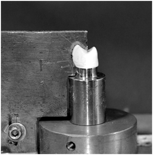
Figure 2. Application of the load aligned with the core-veneer interface, tangentially to the highest point of curvature between the buccal and the occlusal cusps. The dotted line shows three different crack pathways in the interface region; cohesive in the unsupported porcelain, cohesive in the core material or adhesive in the interface.
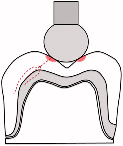
Table 1. Load at fracture.
Figure 3. (A) Fracture surface of MC crown (nr 14) at 30 × magnification (light microscopy); (B) Fracture surface of MC crown (nr 14) at 44 × magnification (SEM).
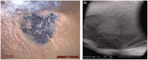
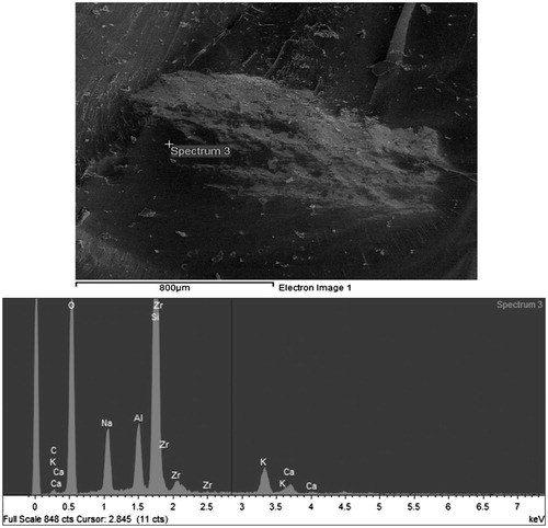
Figure 4. Surface mapping of MC crown (nr 14).
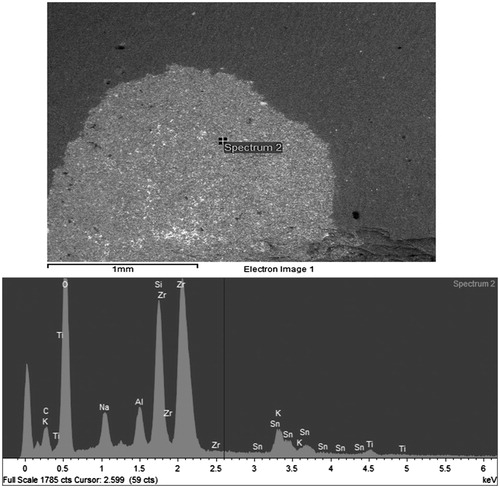
Figure 5. (A) Fracture surface of Y-TZP crown (nr 9) at 30 × magnification (light microscopy); (B) Fracture surface of Y-TZP crown (nr 9) at 45 × magnification (SEM).
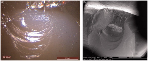
Figure 6. Surface mapping of Y-TZP crown (nr 9).