1,132
Views
6
CrossRef citations to date
0
Altmetric
Technical Papers

Total Diesel Exhaust Particulate Length Measurements Using a Modified Household Smoke Alarm Ionization Chamber

Pages 126-134 | Published online: 10 Oct 2011

Figures & data

Figure 1. Experimental ionization chamber diagram.

Figure 1. Experimental ionization chamber diagram.

Figure 2. Exhaust sampling and measurement setup.

Figure 2. Exhaust sampling and measurement setup.

Figure 3. Comparison of PM emissions measured by the ionization chamber (in arbitrary units) with gravimetric measurement at steady-state engine operation on diesel fuel at various speeds and loads.
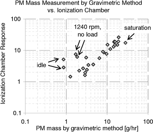
Figure 3. Comparison of PM emissions measured by the ionization chamber (in arbitrary units) with gravimetric measurement at steady-state engine operation on diesel fuel at various speeds and loads.

Figure 4. PM size distribution measured by SMPS and CPC during operation on diesel fuel at idle and at various loads.
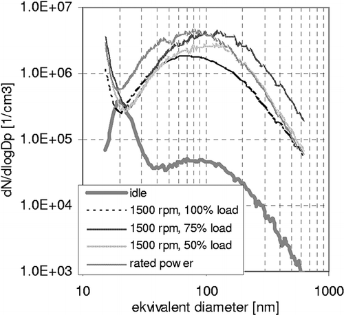
Figure 4. PM size distribution measured by SMPS and CPC during operation on diesel fuel at idle and at various loads.

Figure 5. Comparison of total PM length measured by SMPS and CPC during steady-state engine operation on diesel fuel at various speeds and loads with the ionization chamber response.
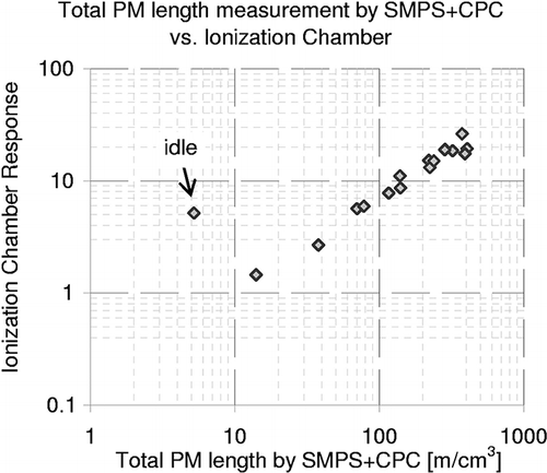
Figure 5. Comparison of total PM length measured by SMPS and CPC during steady-state engine operation on diesel fuel at various speeds and loads with the ionization chamber response.

Figure 6. Comparison of PM emissions measured by the ionization chamber (in arbitrary units) with gravimetric measurement at steady-state engine operation on diesel fuel and on heated fuel-grade rapeseed oil at various speeds and loads.
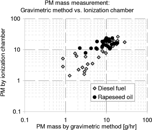
Figure 6. Comparison of PM emissions measured by the ionization chamber (in arbitrary units) with gravimetric measurement at steady-state engine operation on diesel fuel and on heated fuel-grade rapeseed oil at various speeds and loads.

Figure 7. Comparison of total PM length measured by EEPS with the ionization chamber response during a sequence of steady-state operating points run on diesel fuel and heated fuel-grade rapeseed oil with and without a DPF.
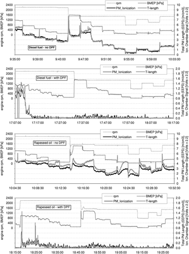
Figure 7. Comparison of total PM length measured by EEPS with the ionization chamber response during a sequence of steady-state operating points run on diesel fuel and heated fuel-grade rapeseed oil with and without a DPF.

Figure 8. Comparison of PM emissions measured by the ionization chamber (in arbitrary units) with total PM length calculated from EEPS measurements during operation on diesel fuel without and with a DPF.
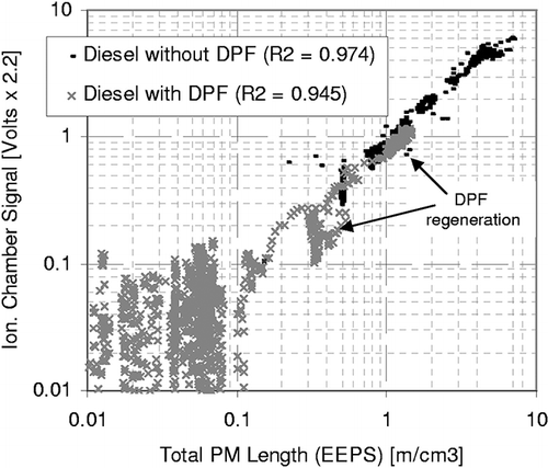
Figure 8. Comparison of PM emissions measured by the ionization chamber (in arbitrary units) with total PM length calculated from EEPS measurements during operation on diesel fuel without and with a DPF.

Table 1. Correlation of the second-by-second signal of the ionization chamber signal with EEPS measurements— operation without DPF

Figure 9. Comparison of PM emissions measured by the ionization chamber (in arbitrary units) with total PM length calculated from EEPS measurements during operation on heated rapeseed oil without and with a DPF.
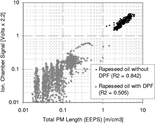
Figure 9. Comparison of PM emissions measured by the ionization chamber (in arbitrary units) with total PM length calculated from EEPS measurements during operation on heated rapeseed oil without and with a DPF.

Figure 10. Comparison of PM emissions measured by the ionization chamber (in arbitrary units) with total PM length calculated from EEPS measurements—all tests.
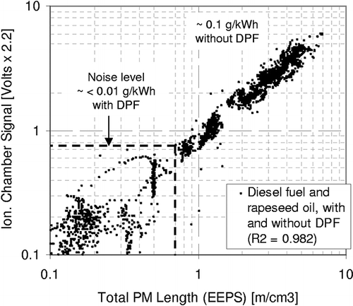
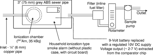
Figure 10. Comparison of PM emissions measured by the ionization chamber (in arbitrary units) with total PM length calculated from EEPS measurements—all tests.

Figure 11. Comparison of PM emissions measured by the ionization chamber (in arbitrary units) with particle number concentration in the 100-nm size range during the ETC transient cycle.

Figure 11. Comparison of PM emissions measured by the ionization chamber (in arbitrary units) with particle number concentration in the 100-nm size range during the ETC transient cycle.

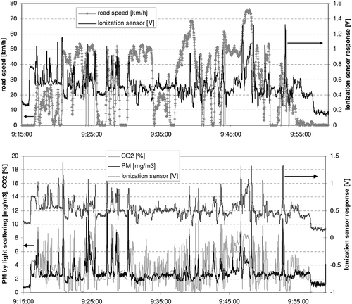
Figure 12. PM emissions measured by the ionization chamber (in arbitrary units) during an urban and suburban operation of a Euro 4 Renault traffic van with a 2-L Common Rail turbodiesel engine plotted with (a) vehicle speed and (b) CO2 and PM mass concentrations.

Figure 12. PM emissions measured by the ionization chamber (in arbitrary units) during an urban and suburban operation of a Euro 4 Renault traffic van with a 2-L Common Rail turbodiesel engine plotted with (a) vehicle speed and (b) CO2 and PM mass concentrations.

Reprints and Corporate Permissions

Please note: Selecting permissions does not provide access to the full text of the article, please see our help page How do I view content?

To request a reprint or corporate permissions for this article, please click on the relevant link below:

Academic Permissions

Please note: Selecting permissions does not provide access to the full text of the article, please see our help page How do I view content?

Obtain permissions instantly via Rightslink by clicking on the button below:

If you are unable to obtain permissions via Rightslink, please complete and submit this Permissions form. For more information, please visit our Permissions help page.