3,257
Views
12
CrossRef citations to date
0
Altmetric
Technical Papers

PM2.5 Emissions from Aluminum Smelters: Coefficients and Environmental Impact

Pages 311-318 | Published online: 10 Oct 2011

Figures & data

Figure 1. Illustration of an electrolysis pot with the raw pot gases recovered and treated at the GTC with alumina. Unrecovered pot gases are vented through the roof of each potroom. This is where CYCLEX, which measures PM2.5 and CPM, is located.
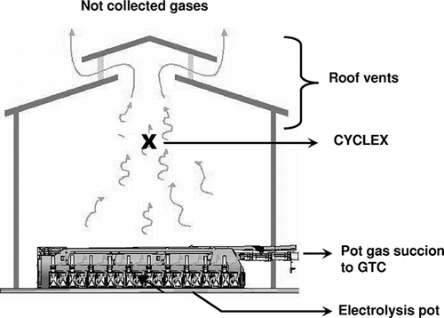
Figure 1. Illustration of an electrolysis pot with the raw pot gases recovered and treated at the GTC with alumina. Unrecovered pot gases are vented through the roof of each potroom. This is where CYCLEX, which measures PM2.5 and CPM, is located.

Figure 2. Picture of the modified PM2.5 sizer for gas recovery in a potroom.

Figure 2. Picture of the modified PM2.5 sizer for gas recovery in a potroom.

Figure 3. Location of Alma smelter and its two air monitoring stations. Arrows indicate the prevailing winds.
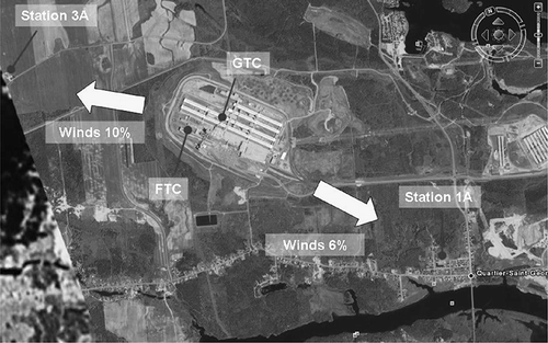
Figure 3. Location of Alma smelter and its two air monitoring stations. Arrows indicate the prevailing winds.

Table 1. Comparisons of mean PM emission coefficients ± standard error of the mean at the Sebree smelter between (1) EPA CTM040/202 and OTM27/28 at GTC and FTC, and between (2) the M14* and Rio Tinto Alcan CYCLEX candidate method at roof vents

Table 2. Ratios of CPM and PM2.5 to PMtotal for the Rio Tinto Alcan Sebree smelter

Table 3. Two-say ANOVA on PM2.5 measuements at roof vents as affected by the year (2007 vs.2008 and the method (M14* vs. CYCLEX)

Table 4. PM2.5 mass fraction of various inorganic species (species mass on the filter/total mass of PM2.5 on the filter—in percent) at the smelter stacks (FTC and GTC) and in its surrounding environment (urban stations 1A and 3 A)

Figure 4. SEM-EDX on GTC and urban station filters. Picture of spotted area on filters and diagram of elemental determination. EDX analysis on (a) the GTC filter, (b) the urban station 1A filter, and (c) the urban station 1A filter.
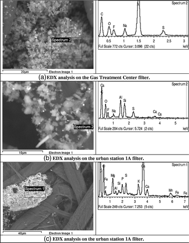
Figure 4. SEM-EDX on GTC and urban station filters. Picture of spotted area on filters and diagram of elemental determination. EDX analysis on (a) the GTC filter, (b) the urban station 1A filter, and (c) the urban station 1A filter.

Figure 5. Lead isotope diagram for samples in the carbon raw material (anode), at the stack output (GTC), and in the surrounding environment of the smelter (station) compared with North American aerosols. Adapted with permission from Poirier.Citation29 Copyright 2006 Elsevier, Earth and Planetary Science Letters.
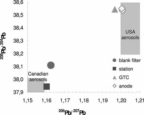
Figure 5. Lead isotope diagram for samples in the carbon raw material (anode), at the stack output (GTC), and in the surrounding environment of the smelter (station) compared with North American aerosols. Adapted with permission from Poirier.Citation29 Copyright 2006 Elsevier, Earth and Planetary Science Letters.

Figure 6. Osmium-lead isotope diagram for samples in the carbon raw material (anode), at the stack output (GTC), and in the surrounding environment of the smelter (station).
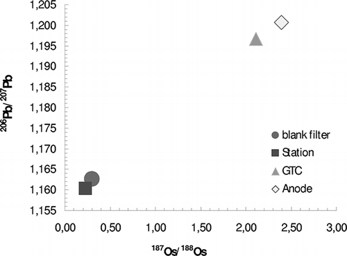
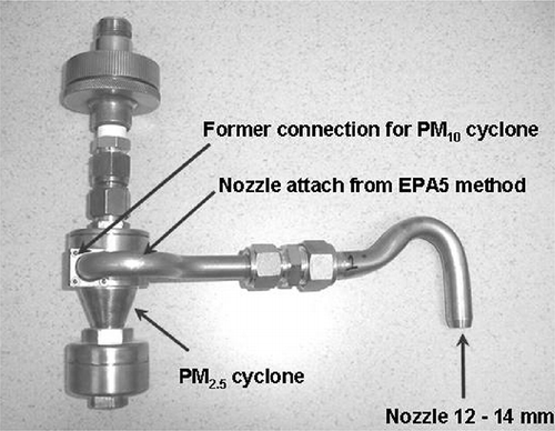
Figure 6. Osmium-lead isotope diagram for samples in the carbon raw material (anode), at the stack output (GTC), and in the surrounding environment of the smelter (station).

Reprints and Corporate Permissions

Please note: Selecting permissions does not provide access to the full text of the article, please see our help page How do I view content?

To request a reprint or corporate permissions for this article, please click on the relevant link below:

Academic Permissions

Please note: Selecting permissions does not provide access to the full text of the article, please see our help page How do I view content?

Obtain permissions instantly via Rightslink by clicking on the button below:

If you are unable to obtain permissions via Rightslink, please complete and submit this Permissions form. For more information, please visit our Permissions help page.