Figures & data
Table 1. ULSD fuel properties used in the ACES program
Table 2. ACES engines ASTM average lube oil properties after 125 hr of engine operation
Figure 1. Overall experimental setup for the ACES program. A= 2007 heavy-duty diesel engine with aftertreatment. B= background bag sample of dilution air for CO, CO2, NOx, NO, THCs, CH4, and C2–C12 speciation. C= regulated PM following CFR Part 1065 using 47-mm Teflo filter. D= impingers for carbonyls, alcohols, ions, and cyanide ion. E= sorbent traps for nitrosamines and Summa canister for SVOCs. F= auxiliary PM samples on 47-mm filters for inorganic ions (Fluoropore filter), XRF (Teflo filter), and inductively coupled MS (Fluoropore filter), DFI/GC (TX-40 filter). G= XAD traps for gas-phase semi-volatile compounds: PAHs, oxyPAHs, nitroPAHs, hopanes, steranes, carpanes, polar organics, high-molecular-weight alkanes and cycloalkanes, dioxins, furans. H= filter (8× 10 in. Zefluor) for particulate-phase semi-volatile compounds: PAHs, oxyPAHs, nitroPAHs, dioxins, furans, hopanes, steranes, carpanes, polar organics, high-molecular-weight alkanes, cycloalkanes, dioxins, and furans. I= UAEC PM mass using Teflo filter, OC/EC collection using a pair of quartz filters, size and number using EEPS, real-time total PM using DMM-230, real-time soot using MSS. J= proportional bag sample for hydrocarbon speciation of C2–C12 compounds. K= Horiba MEXA 7200 for THCs, CO, CO2,NOx, NO analyzer, and CH4 analyzer. L= FTIR for N2O.
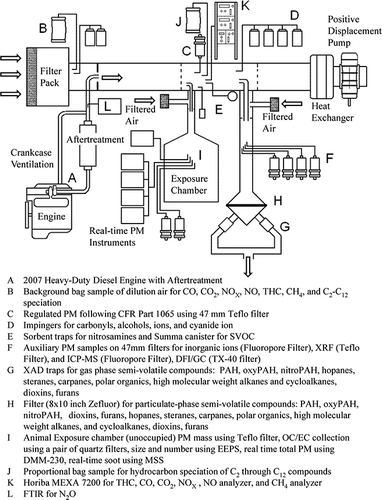
Table 4. Average regulated emissions summary for four FTP composite cycles (1/7 × cold start+ 6/7 × hot start), one per ACES phase 1 2007 engine
Table 5. Average NO2 emissions summary for all 12 repeats of the hot-start FTP transient cycle for all four 2007 ACES engines
Table 6. Summary of average unregulated emissions for all 12 repeats of the 16-hr cycles for all four 2007 ACES engines and for 2004-technology engines used in CRC E55/E59Citation12 (dioxins were compared to 1998 levels).Citation1 Citation3
Table 7. CARB toxic air contaminant average emissions for all 12 repeats of the 16-hr cycles for all four 2007 ACES engines and for 1994- to 2000-technology engines running over the FTP transient cycle.Citation15
Table 8. PAH and nitroPAH average emissions for all 12 repeats of the 16-hr cycles for all four 2007 ACES engines and for a 2000-technology engine running over the FTP transient cycle.Citation16
Table 9. Elemental average emissions for all 12 repeats of the 16-hr cycles for all four 2007 ACES engines and for 1994- to 2000-technology engines running over the FTP transient cycle.Citation15,Citation16
Table 10. Average element emissions rate and composition used in for all 12 repeats of the 16-hr cycles using all four 2007 ACES engines
Figure 3. Average element emissions rate and composition for all 12 repeats of the 16-hr cycles using all four 2007 ACES engines. As a percentage of total PM: sodium (1%), phosphorus (0.6%), calcium (0.5%), iron (0.7%), and zinc (0.1%). Note that the graph shows the percent of total elements and not PM; PM was collected from the full-flow CVS for these analyses.
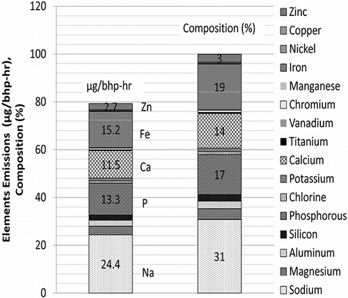
Table 11. Summary of data plotted in
Figure 5. Maximum potential of particle-phase emissions using chemical composition compared with filter weighing and other chemical makeup. Data plotted based on the average emissions for all 12 repeats of the 16-hr cycles using all four 2007 ACES engines. PM for OC/EC was collected from the exposure chamber; PM for sulfate, elements, and gas- and particle-phase semi-volatiles and volatiles were collected from the full-flow CVS.
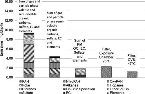
Table 3. Test matrix with the number of repeated runs for each of the four 2007 ACES engines used in the ACES program (only the highlighted events in are reported in this paper)
Figure 2. Average PM emissions rate and composition for all 12 repeats of the 16-hr cycles using all four 2007 ACES engines. The filter for weighing was collected from the exposure chamber using a Teflo filter; OC and EC were collected from the exposure chamber using a quartz filter and analyzed using TOT; and sulfate and elements were collected from a full-flow CVS on fluoropore and Teflo filters, respectively, and were analyzed using ion chromatography and XRF, respectively
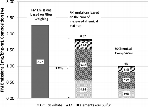
Figure 4. Average particle-phase semi-volatile emissions rate and composition for all 12 repeats of the 16-hr cycles using all four 2007 ACES engines. Particle-phase semi-volatiles were collected from the full-flow CVS.
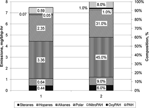
Figure 6. Average particle number emissions comparison between the 2007 ACES engines with and without C-DPF regeneration and a 2004-technology engine. Data for the 2007 ACES engines were based on 12 repeats of the FTP transient cycle and 12 repeats of the 16-hr cycle using all four ACES engines. Data for the 2004-technology engine were based on six repeats of the FTP transient cycle. Data for the 2007 ACES engines were taken from exposure chamber and from full-flow CVS for the 2004-technology engine.
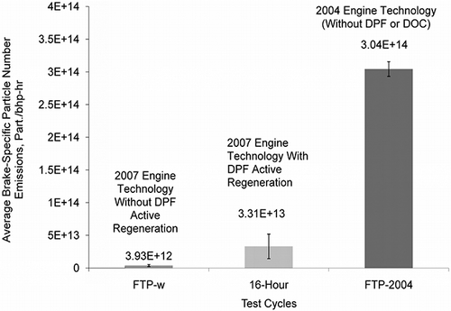
Figure 7. Average size distribution comparison between all 2007 ACES engines with and without C-DPF regeneration and a 2004-technology engine without a DOC and/or a C-DPF. Data for the 2007 ACES engines were taken from the exposure chamber for the 4-hr segments of the 16-hr cycle. Data for the 2004 engine were taken from the full-flow CVS for the FTP transient cycle. GNMD= geometric number mean diameter, GSD= geometric standard deviation.
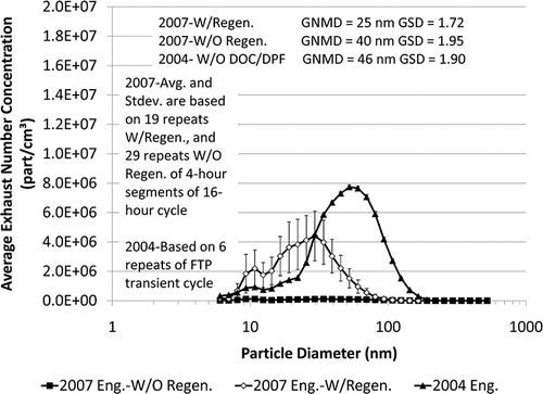
Figure 8. Example of particle number emissions and C-DPF outlet temperature during two separate 4-hr segments of the 16-hr cycle with and without C-DPF active regeneration using one of the ACES engines. Plotted also for comparison are the number emissions from a 2004-technology engine without DOC/C-DPF using the FTP transient cycle. The same FTP data with the 2004-technology engine are plotted in three separate locations to coincide with the FTP transient cycle that is part of the 4-hr segment of the 16-hr cycle.
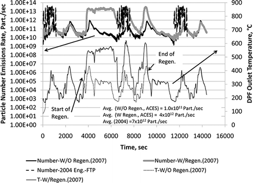
Figure 9. Nuclei-mode particle number in the sub-30-nm size range plotted as a percentage of total particle number during a 4-hr segment of the 16-hr cycle with active C-DPF regeneration. Data are similar to the data shown in for the ACES engine with active regeneration but are plotted as the percentage of total number for sub-30-nm particles.
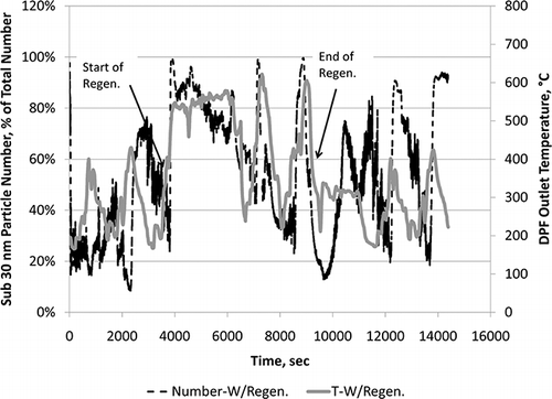
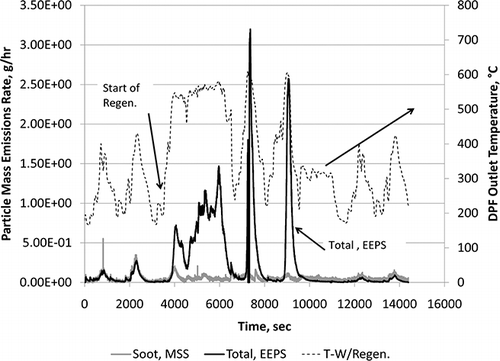
Figure 10. Total and soot particle mass emissions rate profile during a 4-hr segment of the 16-hr cycle with C-DPF active regeneration
