Figures & data
Figure 1. Prosthetic knee with defined reference planes and loading line. (a) Condition I. (b) Condition II.
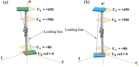
Table 1. P4 loading level for static and cyclic strength test
Figure 2. Model of a prosthetic knee. (a) CAD model. (b) Finite element model.
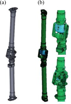
Table 2. Mechanical properties of materials
Figure 3. Prosthetic knee instrumented with strain gauges.
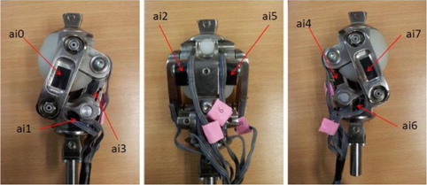
Figure 4. Experimental setup.
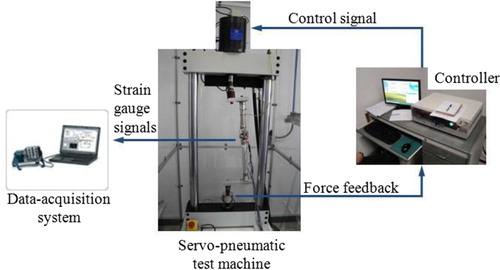
Figure 5. Stress distributions on a prosthetic knee under static strength test. (a) Loading condition I. (b) Loading condition II.
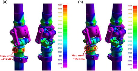
Figure 6. Stress distributions on a prosthetic knee under one loading cycle of cyclic strength test. (a) Loading condition I. (b) Loading condition II.
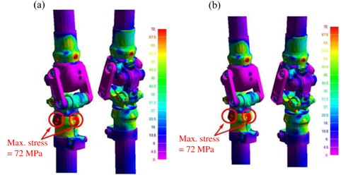
Figure 7. Fatigue strength prediction of a prosthetic knee. (a) Loading condition I. (b) Loading condition II.
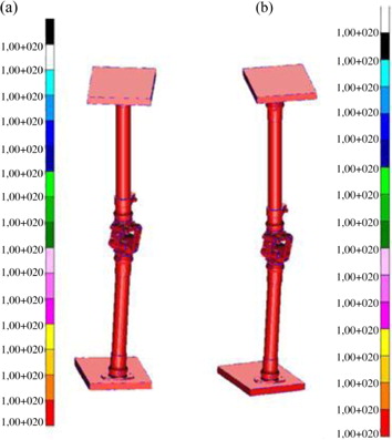
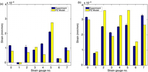
Figure 8. Comparisons of strains obtained from experiments and finite element model under static strength test. (a) Loading condition I. (b) Loading condition II.
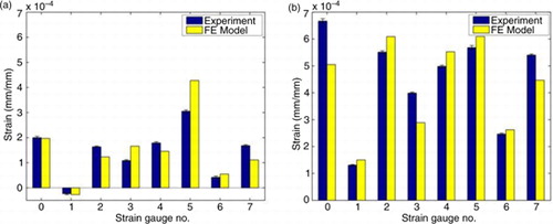
Figure 9. Comparisons of strains obtained from experiments and finite element model under cyclic strength test. (a) Loading condition I. (b) Loading condition II.