2,132
Views
42
CrossRef citations to date
0
Altmetric
Review Series

Part 1: Design, modeling and simulation of post-combustion CO2 capture systems using reactive solvents

, , , &
Pages 265-288 | Published online: 10 Apr 2014

Figures & data

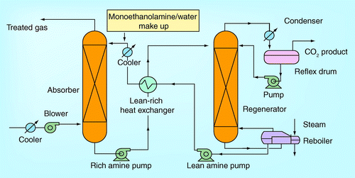
Figure 1.  Typical absorption-based CO2 capture unit.
Figure 2.  Design procedure of CO2 absorber.

(A) Emphirical design method, (B) Theoretical design method, (C) Laboratory method and (D) Pilot plant technique method.

Modified with permission from Citation[20].

Figure 2.  Design procedure of CO2 absorber. (A) Emphirical design method, (B) Theoretical design method, (C) Laboratory method and (D) Pilot plant technique method.Modified with permission from Citation[20].
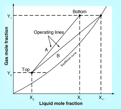
Figure 3.  Solubility plot and operating line.
Figure 4.  Small cell used for laboratory method.

CB: Concentration; G: Gas; L: Liquid; PA: Partial pressure.

Modified with permission from Citation[20].

Figure 4.  Small cell used for laboratory method.CB: Concentration; G: Gas; L: Liquid; PA: Partial pressure.Modified with permission from Citation[20].
Figure 5.  String-of-sphere column Citation[45].

γ: Unit volume of liquid; av: Interfacial area; CB: Concentration; G: Gas; KG; Overall gas mass transfer coeffiecient; KL; Overall liquid mass transfer coeffiecient; L: Liquid; PA: Partial pressure; Z: Height.

Figure 5.  String-of-sphere column Citation[45].γ: Unit volume of liquid; av: Interfacial area; CB: Concentration; G: Gas; KG; Overall gas mass transfer coeffiecient; KL; Overall liquid mass transfer coeffiecient; L: Liquid; PA: Partial pressure; Z: Height.
Figure 6.  Pilot plant technique.

Modified from with permission from Citation[20].

CB: Concentration; G: Gas; L: Liquid; PA: Partial pressure; Zm: Height.

Figure 6.  Pilot plant technique.Modified from with permission from Citation[20].CB: Concentration; G: Gas; L: Liquid; PA: Partial pressure; Zm: Height.
Figure 7.  Pilot plant schematic process flow diagram for (A) ITC, Esbjerg CASTOR and ITT (B) SINTEF/NTNU.

HEX: Heat exchanger; L: Liquid; P: Pump; V: Vapour.

Reproduced with permission from Citation[15].

Figure 7.  Pilot plant schematic process flow diagram for (A) ITC, Esbjerg CASTOR and ITT (B) SINTEF/NTNU.HEX: Heat exchanger; L: Liquid; P: Pump; V: Vapour.Reproduced with permission from Citation[15].
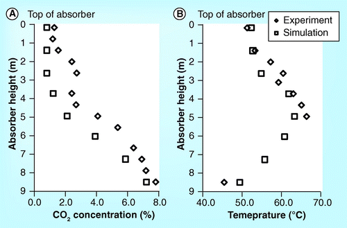
Figure 8.  Experiment and simulation results for (A) CO2 concentration and (B) temperature profiles in the absorber at 8% CO2 content and 90% CO2 capture performance from ITC pilot plant.
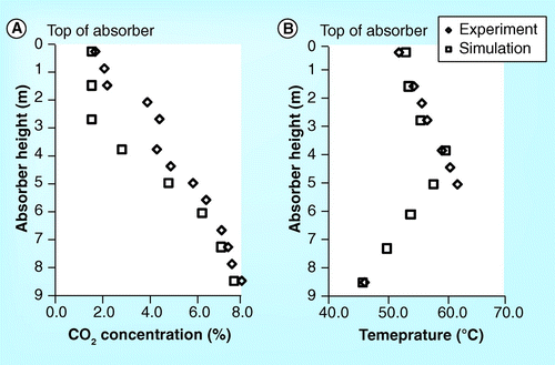
Figure 9.  Experiment and simulation results for (A) CO2 concentration and (B) temperature profiles in the absorber at 8% CO2 content and 80% CO2 capture performance from ITC pilot plant.
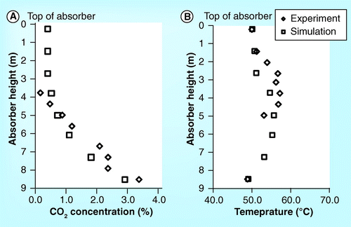
Figure 10.  Experiment and simulation results for (A) CO2 concentration and (B) temperature profiles in the absorber at 4% CO2 content and 90% CO2 capture performance from ITC pilot plant.
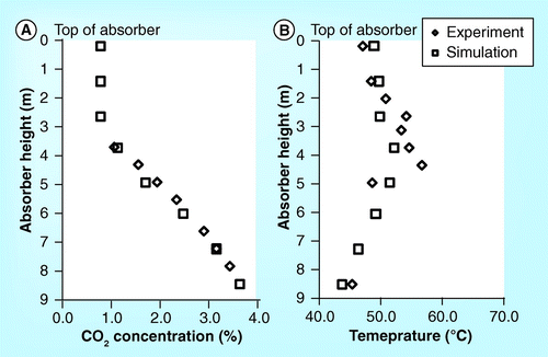
Figure 11.  Experiment and simulation results for (A) CO2 concentration and (B) temperature profiles in the absorber at 4% CO2 content and 80% CO2 capture performance from ITC pilot plant.
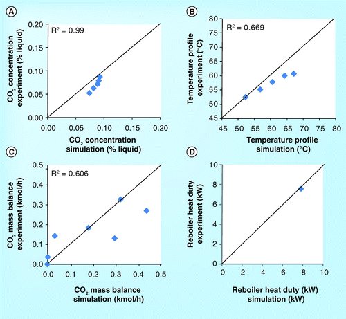
Figure 12.  Parity plots of (A) CO2 concentration (B) temperature profile (C) CO2 mass balance and (D) reboiler heat duty from ITC pilot plant.
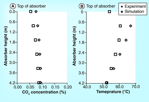
Figure 13.  Experiment and simulation results for (A) CO2 concentration and (B) temperature profiles in the absorber at 11.8% CO2 content and 90% CO2 capture performance from Esbjerg CASTOR pilot plant.
Figure 14.  Parity plots of (A) CO2 concentration (B) tempearature profile (C) CO2 mass balance and (D) reboiler heat duty from Esbjerg CASTOR pilot plant.
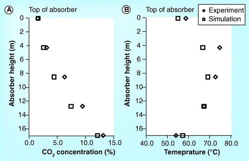
Figure 15.  Experiment and simulation results for (A) CO2 concentration and (B) temperature profiles in the absorber at 13.2% CO2 content and 44% CO2 capture performance from ITT Stuttgart pilot plant.
Figure 16.  Parity plots of (A) CO2 concentration (B) tempearature profile (C) CO2 mass balance and (D) reboiler heat duty from ITT Stuttgart pilot plant.
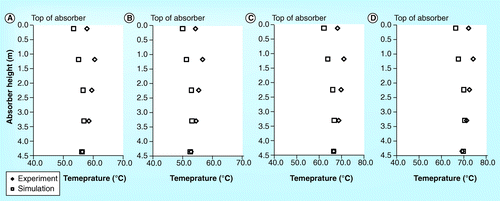
Figure 17.  Experiment and simulation results for temperature profile in the absorber at (A) 2.5% CO2 content and 78.5% CO2 capture performance, (B) 2.6% CO2 content and 58.3% CO2 capture performance, (C) 5.3% CO2 content and 58.1% CO2 capture performance and (D) 9.48% CO2 content and 49.1% CO2 capture performance from SINTEF/NTNU pilot plant.
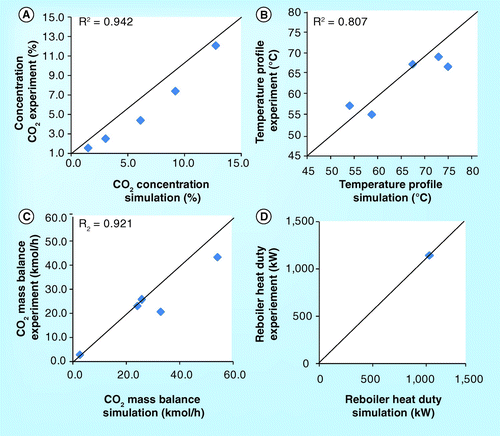
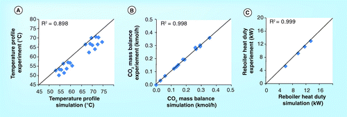
Figure 18.  Parity plots of (A) tempearature profile (B) CO2 mass balance and (C) reboiler heat duty from SINTEF/NTNU pilot plant.
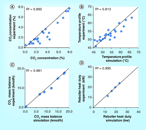
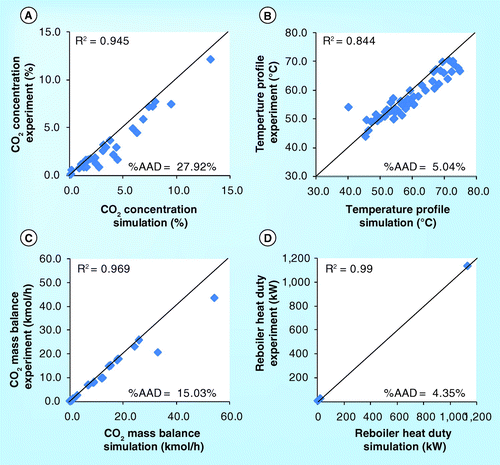
Figure 19.  Parity plots of (A) CO2 concentration (B) tempearature profile (C) CO2 mass balance and (D) reboiler heat duty from ITC, Esbjerg CASTOR, ITT and SINTEF/NTNU pilot plants.
Figure 20a.  (A) An integration of CO2 capture into pulverized coal-fired power plant.

G: Generator; HX: Heat exchanger; PM: Particulate matter; RH: Reheater; SH: Superheater.

Modified with permission from Citation[16].

Figure 20a.  (A) An integration of CO2 capture into pulverized coal-fired power plant.G: Generator; HX: Heat exchanger; PM: Particulate matter; RH: Reheater; SH: Superheater.Modified with permission from Citation[16].
Figure 20b.  (B) An integration of CO2 capture into combined cycle gas turbine power plant.

Comp: Compressor; G: Generator; GT: Gar turbine; HP: High-pressure turbine; HX: Heat exchanger; IP: Intermediate-pressure turbine; LP: Low-pressure turbine.
Bolded numbers 1–4 indicate a connection of each stream line.

Modified with permission from Citation[50].

Figure 20b.  (B) An integration of CO2 capture into combined cycle gas turbine power plant.Comp: Compressor; G: Generator; GT: Gar turbine; HP: High-pressure turbine; HX: Heat exchanger; IP: Intermediate-pressure turbine; LP: Low-pressure turbine.Bolded numbers 1–4 indicate a connection of each stream line.Modified with permission from Citation[50].
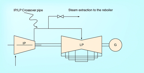
Figure 21.  Intermediate pressure/low pressure crossover pipe.

G: Generator; IP: Intermediate-pressure turbine; LP: Low-pressure turbine.
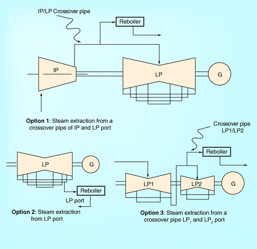
Figure 21.  Intermediate pressure/low pressure crossover pipe.G: Generator; IP: Intermediate-pressure turbine; LP: Low-pressure turbine.
Figure 22.  Steam extraction from low pressure turbine.

G: Generator; IP: Intermediate-pressure turbine; LP: Low-pressure turbine.

Figure 22.  Steam extraction from low pressure turbine.G: Generator; IP: Intermediate-pressure turbine; LP: Low-pressure turbine.

Table 1.  Brief description of process parameters in four different pilot plants.
Reprints and Corporate Permissions

Please note: Selecting permissions does not provide access to the full text of the article, please see our help page How do I view content?

To request a reprint or corporate permissions for this article, please click on the relevant link below:

Academic Permissions

Please note: Selecting permissions does not provide access to the full text of the article, please see our help page How do I view content?

Obtain permissions instantly via Rightslink by clicking on the button below:

If you are unable to obtain permissions via Rightslink, please complete and submit this Permissions form. For more information, please visit our Permissions help page.