1,587
Views
25
CrossRef citations to date
0
Altmetric
RESEARCH PAPER

An analytical model of memristors in plants

, &
Article: e972887 | Received 13 Jul 2014, Accepted 23 Jul 2014, Published online: 22 Dec 2014

Figures & data

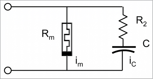
Figure 1. Electrical circuit.

Figure 1. Electrical circuit.

Figure 2. Graphical representation of equations 20 (A) and 25 (B) for the steady state resistance h(V), which depends on voltage V in a linear (A) or quadratic (B) way.
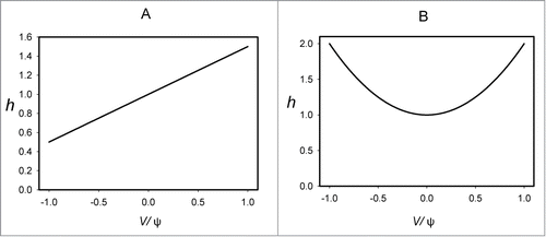
Figure 2. Graphical representation of equations 20 (A) and 25 (B) for the steady state resistance h(V), which depends on voltage V in a linear (A) or quadratic (B) way.

Figure 3. Total electrical current trough a memristor and a capacitor as a function of applied voltage estimated from equations (18, 19 and 24) at different frequencies of a bipolar periodic sinusoidal wave: (A) ωτ = 0.3; (B) ωτ = 1; (C) ωτ = 10, and (D) ωτ = 100.
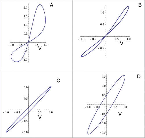
Figure 3. Total electrical current trough a memristor and a capacitor as a function of applied voltage estimated from equations (18, 19 and 24) at different frequencies of a bipolar periodic sinusoidal wave: (A) ωτ = 0.3; (B) ωτ = 1; (C) ωτ = 10, and (D) ωτ = 100.

Figure 4. Total electrical current trough a memristor and a capacitor as a function of applied voltage estimated from equations (18, 19 and 28) at different frequencies of a bipolar periodic sinusoidal wave: (A) ωτ = 0.01; (B) ωτ = 0.1; (C) ωτ = 1, and (D) ωτ = 10.
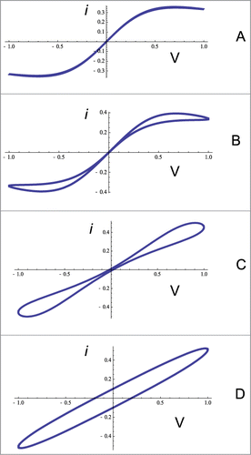
Figure 4. Total electrical current trough a memristor and a capacitor as a function of applied voltage estimated from equations (18, 19 and 28) at different frequencies of a bipolar periodic sinusoidal wave: (A) ωτ = 0.01; (B) ωτ = 0.1; (C) ωτ = 1, and (D) ωτ = 10.

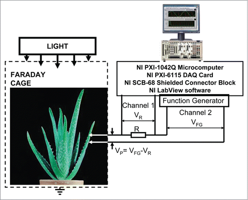
Figure 5. Block diagram of the data acquisition and electrostimulation system.

Figure 5. Block diagram of the data acquisition and electrostimulation system.

Figure 6. Electrical current I versus voltage VP applied across a pulvinus of Mimosa pudica plant. Frequency of periodic bipolar sinusoidal voltage scanning was 1000 Hz (A), 100 Hz (B), 0.001 Hz (C) and 0.0001 Hz (D). Position of Pt electrodes in the pulvinus of Mimosa pudica is shown. These results were reproduced 16 times.
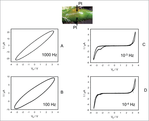
Figure 6. Electrical current I versus voltage VP applied across a pulvinus of Mimosa pudica plant. Frequency of periodic bipolar sinusoidal voltage scanning was 1000 Hz (A), 100 Hz (B), 0.001 Hz (C) and 0.0001 Hz (D). Position of Pt electrodes in the pulvinus of Mimosa pudica is shown. These results were reproduced 16 times.

Figure 7. Cyclic voltammetry along a pulvinus after injection of 0.05 mL of 10 mM TEACl in a stem above and below of the pulvinus 5 hours before electrical measurements. Frequency of sinusoidal voltage scanning was 0.001 Hz (A) or 1000 Hz (B). Position of Pt electrodes in the pulvinus of Mimosa pudica are shown.
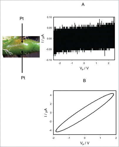
Figure 7. Cyclic voltammetry along a pulvinus after injection of 0.05 mL of 10 mM TEACl in a stem above and below of the pulvinus 5 hours before electrical measurements. Frequency of sinusoidal voltage scanning was 0.001 Hz (A) or 1000 Hz (B). Position of Pt electrodes in the pulvinus of Mimosa pudica are shown.

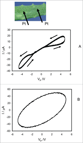
Figure 8. Cyclic voltammetry of a leaf of Aloe vera. Frequency of periodic bipolar sinusoidal voltage scanning was 0.001 Hz (A) and 1000 Hz (B). Position of Pt electrodes in a leaf of Aloe vera is shown. These results were reproduced 16 times.

Figure 8. Cyclic voltammetry of a leaf of Aloe vera. Frequency of periodic bipolar sinusoidal voltage scanning was 0.001 Hz (A) and 1000 Hz (B). Position of Pt electrodes in a leaf of Aloe vera is shown. These results were reproduced 16 times.