Figures & data
Figure 1. Schematic of the perfusion system described by Bancroft et al. (A) Top view of the perfusion chamber with six scaffold holders. (B) Representation of the complete system with the scaffold represented in gray, press-fit between the two O-rings, in black. The two medium reservoirs, 1 and 2, allow for complete medium change when the connection between the two is closed. Arrows represent medium flow.
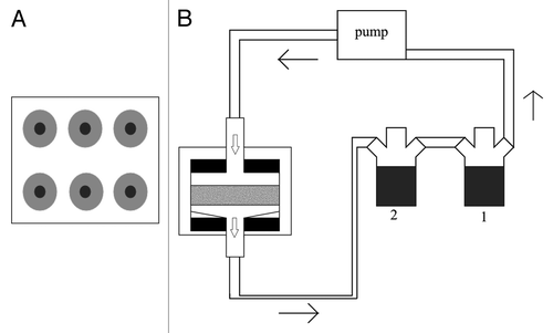
Figure 2. Schematic of the perfusion system described by Janssen et al. (A) Top view of the perforated lid and bottom, (B) detail of the perfusion chamber (scaffolds in gray and O-rings in black) and (C) representation of the complete system. Oxygen sensors are placed before and after the perfusion chamber.
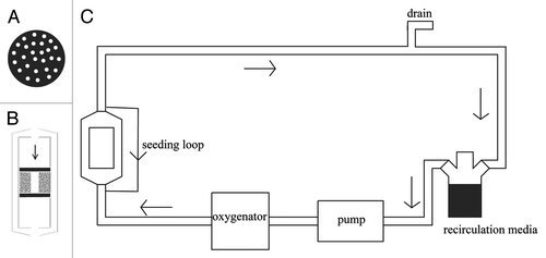
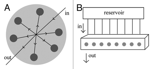
Figure 3. (A) Representation of the perfusion chamber described by Grayson et al.Citation32 The media goes in through one end and it is distributed equally by the six individual chambers (each holding one scaffold shown in gray) and finally goes out through the opposite end. (B) Representation of the system described by Cartmell et al.Citation62 The perfusion block is composed by eight individual chambers (each holding one scaffold, entrance of the chamber shown in gray). Each chamber is fed individually by a tube that comes from the reservoir.