381
Views
8
CrossRef citations to date
0
Altmetric
Mini Review

Static and dynamic snapshots for goal localization in insects?

Pages 17-20 | Received 27 Sep 2010, Accepted 27 Sep 2010, Published online: 01 Jan 2011

Figures & data

Figure 1 In our study honeybees were trained to visit a perspex feeder surrounded by three landmarks (diameter of 5 cm, height of 25 cm) placed at different distances (10, 20, 40 cm) from the feeder in a circular flight arena (diameter of 195 cm; height of 50 cm).Citation18 (A) During training the landmarks were covered with a homogeneous texture providing luminance contrast to the background. (B) After being trained with three homogenous textured landmarks, honeybees were tested individually with landmarks that had the same random dot texture as the background of the arena. (C) The top view shows an example flight trajectory of a honeybee. Approach flights to the feeder (black circle) surrounded by three landmarks (grey circles) were recorded with three high-speed cameras at 125 fps. The position of the bee is indicated by grey circles at each 32 ms interval; straight lines indicate the orientation of the long axis of the bee. The inset shows a sideways-directed flight manoeuvre of a honeybee close to the landmark (two times magnified; Reproduced from ref. Citation18). (D) shows an optic flow snapshot calculated at the feeder position. White indicates high optic flow amplitudes. The landmarks “pop out” of the background although they have the same texture as the background (B). From a 3D model of the arena, panoramic images were rendered at 1°/pixel resolution. Optic flow fields were generated by simulated translations of 2 mm in the flight arena, obtaining four images at (x ± 1 mm, y), (x, y ± 1 mm). The optic flow for these movements was computed using a modified version of the Lucas-Kanade algorithm. To generate flow amplitudes independent of the direction of motion, flow fields for the two steps (in x and y) were squared and summed.Citation18 The optic flow snapshot implicitly contains information about the depth structure of the scene, as closer objects move faster and create a higher optic flow amplitude. This can be seen by comparing the near landmark in the centre of the picture to the middle far (left) and the far (right) landmark.
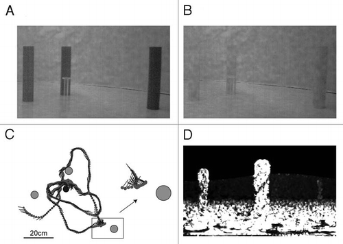
Figure 1 In our study honeybees were trained to visit a perspex feeder surrounded by three landmarks (diameter of 5 cm, height of 25 cm) placed at different distances (10, 20, 40 cm) from the feeder in a circular flight arena (diameter of 195 cm; height of 50 cm).Citation18 (A) During training the landmarks were covered with a homogeneous texture providing luminance contrast to the background. (B) After being trained with three homogenous textured landmarks, honeybees were tested individually with landmarks that had the same random dot texture as the background of the arena. (C) The top view shows an example flight trajectory of a honeybee. Approach flights to the feeder (black circle) surrounded by three landmarks (grey circles) were recorded with three high-speed cameras at 125 fps. The position of the bee is indicated by grey circles at each 32 ms interval; straight lines indicate the orientation of the long axis of the bee. The inset shows a sideways-directed flight manoeuvre of a honeybee close to the landmark (two times magnified; Reproduced from ref. Citation18). (D) shows an optic flow snapshot calculated at the feeder position. White indicates high optic flow amplitudes. The landmarks “pop out” of the background although they have the same texture as the background (B). From a 3D model of the arena, panoramic images were rendered at 1°/pixel resolution. Optic flow fields were generated by simulated translations of 2 mm in the flight arena, obtaining four images at (x ± 1 mm, y), (x, y ± 1 mm). The optic flow for these movements was computed using a modified version of the Lucas-Kanade algorithm. To generate flow amplitudes independent of the direction of motion, flow fields for the two steps (in x and y) were squared and summed.Citation18 The optic flow snapshot implicitly contains information about the depth structure of the scene, as closer objects move faster and create a higher optic flow amplitude. This can be seen by comparing the near landmark in the centre of the picture to the middle far (left) and the far (right) landmark.