609
Views
5
CrossRef citations to date
0
Altmetric
Perspective

Run-length encoding graphic rules, biochemically editable designs and steganographical numeric data embedment for DNA-based cryptographical coding system

Article: e23478 | Published online: 01 Mar 2013

Figures & data

Figure 1. The proposed structures of the DNA fragments coding for the images. (A) Chemical structure of DNA (only single stranded form is shown). (B) Schematic model for the structure of a gene and regulatory sequences coded on DNA. (C) Schematic model for the structure of an “image-coding DNA unit” newly proposed here. The numbers, 5′ and 3′ at the ends of DNA indicate the orientation of the chains (coding and reading start from 5′-terminal toward the 3′-terminal). Black box at the center of the DNA chain stands for the image coding region. Within the white box corresponding to the non-coding regions, five different elements are embedded namely: (1) the positional markers; (2) the tags for DNA-based “password” editing procedures such as cutting and pasting; (3) the starting points and end points for the copying events; (4) the labeling required for filing (or addressing); and (5) embedment of hidden information (e.g., steganography).
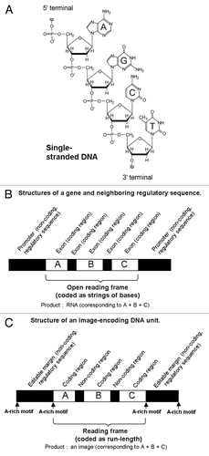
Figure 1. The proposed structures of the DNA fragments coding for the images. (A) Chemical structure of DNA (only single stranded form is shown). (B) Schematic model for the structure of a gene and regulatory sequences coded on DNA. (C) Schematic model for the structure of an “image-coding DNA unit” newly proposed here. The numbers, 5′ and 3′ at the ends of DNA indicate the orientation of the chains (coding and reading start from 5′-terminal toward the 3′-terminal). Black box at the center of the DNA chain stands for the image coding region. Within the white box corresponding to the non-coding regions, five different elements are embedded namely: (1) the positional markers; (2) the tags for DNA-based “password” editing procedures such as cutting and pasting; (3) the starting points and end points for the copying events; (4) the labeling required for filing (or addressing); and (5) embedment of hidden information (e.g., steganography).

Figure 2. The model “password” to be ciphered as the fragments of DNA-encoded images. (A) Within the 9 × 9 blocks, the letters A (left), D (middle) and N (right), were coded as the two-toned images. (B) Strings of numbers (1, black; 0, white) directly reflecting the structures of the font images.
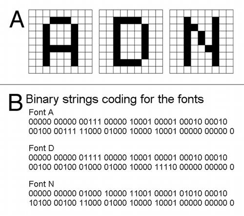
Figure 2. The model “password” to be ciphered as the fragments of DNA-encoded images. (A) Within the 9 × 9 blocks, the letters A (left), D (middle) and N (right), were coded as the two-toned images. (B) Strings of numbers (1, black; 0, white) directly reflecting the structures of the font images.

Figure 3. The model “password” encoded by a RLE system (Wyle encoding system). (A) The run-lengths consisting the fonts of model letters A (left), D (middle) and N defined on the 9 × 9 block-square were counted. (B) The blocks of black and white colors were converted to run-lengths. The numbers shown are in decimal. (C) The run-lengths forming the letter fonts were expressed with Wyle encoding system. Boxed numbers, prefixes, other number, run-length. The numbers shown are binary.
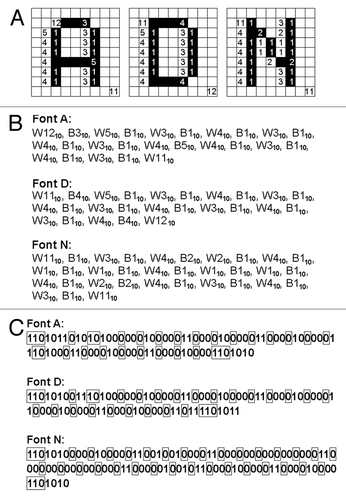
Figure 3. The model “password” encoded by a RLE system (Wyle encoding system). (A) The run-lengths consisting the fonts of model letters A (left), D (middle) and N defined on the 9 × 9 block-square were counted. (B) The blocks of black and white colors were converted to run-lengths. The numbers shown are in decimal. (C) The run-lengths forming the letter fonts were expressed with Wyle encoding system. Boxed numbers, prefixes, other number, run-length. The numbers shown are binary.

Figure 4. Wyle encoding system-based Run-length encoding approaches using DNA. (A) Prototype code 0.1. Note that 1 and 0 in wyle encoding system are simply converted to T and C. Prefixes are boxed. (B) Prototype code 0.2. Again, prefixes are boxed. The prefixes preceding the run-length codes are expressed with single guanine base, G. (C) Prototype code 0.3. Outlined letters indicate the positions shorten by new coding rule.
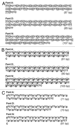
Figure 4. Wyle encoding system-based Run-length encoding approaches using DNA. (A) Prototype code 0.1. Note that 1 and 0 in wyle encoding system are simply converted to T and C. Prefixes are boxed. (B) Prototype code 0.2. Again, prefixes are boxed. The prefixes preceding the run-length codes are expressed with single guanine base, G. (C) Prototype code 0.3. Outlined letters indicate the positions shorten by new coding rule.

Figure 5. Use of length-less (zero-length) runs. (A) New rule was proposed for coding the run without length by inserting the one-binary shift in the codes. (B) Insertion of the length-less runs into the existing runs without distortion of ceded images.
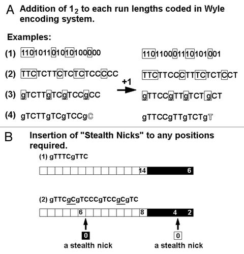
Figure 5. Use of length-less (zero-length) runs. (A) New rule was proposed for coding the run without length by inserting the one-binary shift in the codes. (B) Insertion of the length-less runs into the existing runs without distortion of ceded images.

Figure 6. Taylor-made PCR for introducing the restriction sites of interest for designed DNA-chain conjugation. Note that the presence of complementary chains of DNA is not shown on the illustrations for simplification. (A) Separately coded letter images and a list of uncountable choices (likely passwords). (B) Preparation of PCR primers for designed DNA digestion. (C) Restriction enzyme recognizition sites PCR-dependently created at terminals of DNA. (D) Digestion by selected restriction enzymes. (E) Formation of novel molecule during the “password” decoding process. M, E and H strand for marginal regions, EcoR I recognition sites and Hind III recognitions sites, respectively.
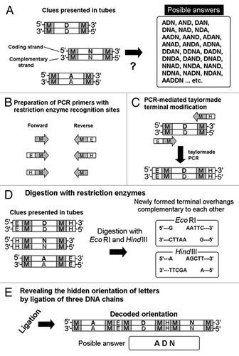
Figure 6. Taylor-made PCR for introducing the restriction sites of interest for designed DNA-chain conjugation. Note that the presence of complementary chains of DNA is not shown on the illustrations for simplification. (A) Separately coded letter images and a list of uncountable choices (likely passwords). (B) Preparation of PCR primers for designed DNA digestion. (C) Restriction enzyme recognizition sites PCR-dependently created at terminals of DNA. (D) Digestion by selected restriction enzymes. (E) Formation of novel molecule during the “password” decoding process. M, E and H strand for marginal regions, EcoR I recognition sites and Hind III recognitions sites, respectively.

Figure 7. Designing the common terminal structures for all of the letter-coding DNA chains by insertions of the pair of G (guanine used as a gap) and C (cytosine) as a “stealth nick” within the font-coding reading frames. After insertions of gC to Font A and Font D, at 5′-termini and at 3′-termini, the sequences gTCTTg and gTCTT, respectively, are common to all DNA chains.
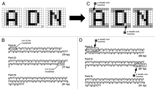
Figure 7. Designing the common terminal structures for all of the letter-coding DNA chains by insertions of the pair of G (guanine used as a gap) and C (cytosine) as a “stealth nick” within the font-coding reading frames. After insertions of gC to Font A and Font D, at 5′-termini and at 3′-termini, the sequences gTCTTg and gTCTT, respectively, are common to all DNA chains.

Figure 8. DNA-encoded image-based steganography. (A) Generalized concept for steganography overlying the numbers of interest under the media (cover media). (B) DNA RLE-based steganographic approach.
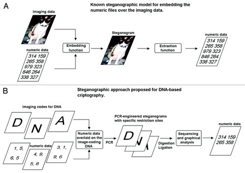
Figure 8. DNA-encoded image-based steganography. (A) Generalized concept for steganography overlying the numbers of interest under the media (cover media). (B) DNA RLE-based steganographic approach.

Figure 9. Steganographic insertion of stealth nicks (gC)s into the font image-coding DNA sequences used as cover media (A, D and N), at the positions corresponding to numeric codes. (A) Insertion of stealth nicks into the font images coded by DNA. Coded image even after insertion of stealth nicks (left). Images visualizing the position of stealth nick insertions (right). (B) Steganographically modified DNA sequences coding for the font images (A, D and N) with RLE. Italicized letters indicate the insertion of stealth nicks into the original DNA sequences.
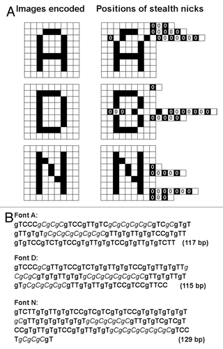
Figure 9. Steganographic insertion of stealth nicks (gC)s into the font image-coding DNA sequences used as cover media (A, D and N), at the positions corresponding to numeric codes. (A) Insertion of stealth nicks into the font images coded by DNA. Coded image even after insertion of stealth nicks (left). Images visualizing the position of stealth nick insertions (right). (B) Steganographically modified DNA sequences coding for the font images (A, D and N) with RLE. Italicized letters indicate the insertion of stealth nicks into the original DNA sequences.

Table 1. Hidden numbers steganographically encoded by the positions of stealth nick inserted into the DNA RLEs coding for the font images

Table 2. Comparison of data compressing RLE protocols for DNA-coded images