Figures & data
Figure 1 Cartoon of three different FtsZ suprastructures. (A) Straight filaments. (B) Helical filaments. (C) Toroids. Blue and red subunits illustrate two different conformations of the monomer. The transformation between the different supramolecular structures is caused by changes between the bistable conformations, due to a shift of local conditions (pH or ions). The inner diameter of rings and toroids is ∼200 nm, which could be an energy minimized state during Z-ring constriction.
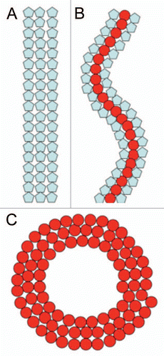
Figure 2 Schematic model of ParM bundles. Three filaments with their pointed ends (p) up are shown in yellow one filament with the barbed end (b) up is shown in tan. Parallel filaments within the bundle (filaments 1–2) share similar large areas of molecular interaction (illustrated as red and green patches) as filaments arranged anti-parallel (filaments 2–3 or 3–4).
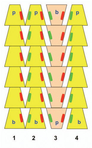
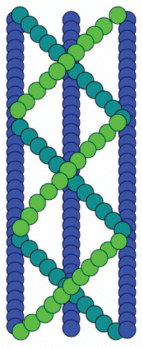
Figure 3 Schematic diagram of the molecular arrangement of interwoven MreB filaments within cables.