792
Views
21
CrossRef citations to date
0
Altmetric
Research Paper

Fine structure of the "PcG body" in human U-2 OS cells established by correlative light-electron microscopy

Pages 219-228 | Received 04 Feb 2011, Accepted 05 Apr 2011, Published online: 01 May 2011

Figures & data

Figure 1 Correlation of live cell imaging and fluorescence immunocytochemistry, and correlation of “PcG bodies” fluorescence with DA/DAPI staining and DNA immunofluorescence. (A1) U-2 OS BMI1-GFP cells were imaged in vivo in gridded Petri dishes. Live cell images are shown consecutively: localization of the cells in phase contrast, with the chosen cell of the interest being delineated in the rectangle (overview phase), differential interference contrast microscopy of the cell of interest (DIC), and Z-projection of fluorescence of GFP-tagged BMI1 protein in the same cell (in vivo GFP). (A2) Subsequently, the cells were aldehyde fixed, permeabilized and immunolabeled with antibodies. Maximum intensity projections of BMI1 (BMI1) and GFP (GFP) signals are shown. DNA was counterstained with DAPI (DAPI, middle confocal section). The in vivo fluorescence signal of the PcG bodies matches well both the BMI1 and GFP immunofluorescence signals. (B) Counterstaining of the fixed and permeabilized U-2 OS BMI1-GFP cells with DAPI in combination with distamycin A (DA/DAPI) to show the co-localization of increased DNA density with the PcG bodies identified with an anti-GFP antibody (GFP). The highest intensities of DA/DAPI fluorescence on maximum intensity projection co-localized with the fluorescence of the PcG bodies (white arrows). (C) Live cell imaging of the PcG bodies (in vivo GFP) was, after weak fixation accompanied by the use of 2% Triton X-100 treatment, correlated with the GFP (GFP) and DNA (DNA) immunocytochemistry images. The anti-DNA labeling revealed a high accumulation of DNA in the PcG bodies (white arrows).
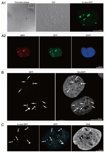
Figure 1 Correlation of live cell imaging and fluorescence immunocytochemistry, and correlation of “PcG bodies” fluorescence with DA/DAPI staining and DNA immunofluorescence. (A1) U-2 OS BMI1-GFP cells were imaged in vivo in gridded Petri dishes. Live cell images are shown consecutively: localization of the cells in phase contrast, with the chosen cell of the interest being delineated in the rectangle (overview phase), differential interference contrast microscopy of the cell of interest (DIC), and Z-projection of fluorescence of GFP-tagged BMI1 protein in the same cell (in vivo GFP). (A2) Subsequently, the cells were aldehyde fixed, permeabilized and immunolabeled with antibodies. Maximum intensity projections of BMI1 (BMI1) and GFP (GFP) signals are shown. DNA was counterstained with DAPI (DAPI, middle confocal section). The in vivo fluorescence signal of the PcG bodies matches well both the BMI1 and GFP immunofluorescence signals. (B) Counterstaining of the fixed and permeabilized U-2 OS BMI1-GFP cells with DAPI in combination with distamycin A (DA/DAPI) to show the co-localization of increased DNA density with the PcG bodies identified with an anti-GFP antibody (GFP). The highest intensities of DA/DAPI fluorescence on maximum intensity projection co-localized with the fluorescence of the PcG bodies (white arrows). (C) Live cell imaging of the PcG bodies (in vivo GFP) was, after weak fixation accompanied by the use of 2% Triton X-100 treatment, correlated with the GFP (GFP) and DNA (DNA) immunocytochemistry images. The anti-DNA labeling revealed a high accumulation of DNA in the PcG bodies (white arrows).

Figure 2 CLEM of high pressure frozen and cryosubstituted cells (the images of the same cell are also shown in ; however, encompasses different thin sections and documents images of a different “PcG body” in this same cell). U-2 OS BMI1-GFP cells grown on the sapphire discs were clamped in the live cell carrier with the finder grid and imaged face down. After live cell imaging the cells were high-pressure frozen, cryosubstituted and immunolabeled with anti-BMI1 antibody. In fluorescence and EM images in and , the white and yellow arrows point to a nuclear region/domain corresponding to the two GFP “PcG bodies”. Invaginations of the nuclear envelope are designated by black arrows and arrowheads. (A) An overview image (merge of fluorescence and phase contrast) to determine the quadrant of interest on the finder grid, (B) higher magnification of the quadrant with the cells of interest delineated in the rectangle. (B1) Phase contrast and (B2) maximum intensity projection of fluorescence of the cells from the rectangle. (C) The same two thin sectioned cells seen in the electron microscope. Some of the serial thin sections we also processed for on-section fluorescence immunocytochemistry (see inserts in and C as well as Sup. Figs. 35 in the Sup. Material). (D) Anti-BMI1 immunogold labeling on ultrathin sections (15 nm gold particles). The electron-dense heterochromatin structures (he) are specifically enriched in the BMI1 immunogold label while the cytoplasm (cy) rich in ribosomes is devoid of the label. The nucleolus (nu) in the insert of shows two BMI1 labeled intranucleolar heterochromatin clumps (white arrowheads). The white arrow points to a nuclear region/domain that correlates with (a section of) the “PcG body” fluorescence seen in , with the local accumulation of heterochromatin structures in this domain.
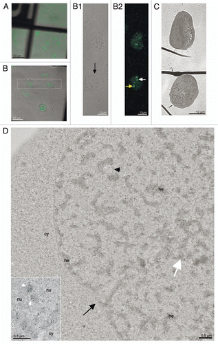
Figure 2 CLEM of high pressure frozen and cryosubstituted cells (the images of the same cell are also shown in Fig. 3; however, Fig. 3 encompasses different thin sections and documents images of a different “PcG body” in this same cell). U-2 OS BMI1-GFP cells grown on the sapphire discs were clamped in the live cell carrier with the finder grid and imaged face down. After live cell imaging the cells were high-pressure frozen, cryosubstituted and immunolabeled with anti-BMI1 antibody. In fluorescence and EM images in Figures 2 and 3, the white and yellow arrows point to a nuclear region/domain corresponding to the two GFP “PcG bodies”. Invaginations of the nuclear envelope are designated by black arrows and arrowheads. (A) An overview image (merge of fluorescence and phase contrast) to determine the quadrant of interest on the finder grid, (B) higher magnification of the quadrant with the cells of interest delineated in the rectangle. (B1) Phase contrast and (B2) maximum intensity projection of fluorescence of the cells from the rectangle. (C) The same two thin sectioned cells seen in the electron microscope. Some of the serial thin sections we also processed for on-section fluorescence immunocytochemistry (see inserts in Fig. 3B and C as well as Sup. Figs. 3–5 in the Sup. Material). (D) Anti-BMI1 immunogold labeling on ultrathin sections (15 nm gold particles). The electron-dense heterochromatin structures (he) are specifically enriched in the BMI1 immunogold label while the cytoplasm (cy) rich in ribosomes is devoid of the label. The nucleolus (nu) in the insert of Figure 2D shows two BMI1 labeled intranucleolar heterochromatin clumps (white arrowheads). The white arrow points to a nuclear region/domain that correlates with (a section of) the “PcG body” fluorescence seen in Figure 2B2, with the local accumulation of heterochromatin structures in this domain.

Figure 3 CLEM of a high pressure frozen, cryosubstituted and serially sectioned cell. (A) Anti-BMI1 immunogold labeling of heterochromatin structures (15 nm gold particles) of the same cell as in the , but a different thin section is shown in (A). The yellow arrow points to the nuclear region/domain that correlates with (the section of) the “PcG body” fluorescence seen in 2 with the local density of heterochromatin structures being enriched in this domain. The heterochromatin structures are specifically enriched in the BMI1 immunogold label. Gold particles are sometimes situated towards the periphery of the heterochromatin structures (insert). (B–E) Four consecutive serial sections from the same area as shown in (A). In (B and C), the thin sections were first used for on-section immunofluorescence mapping of the BMI1 protein (inserts; note that the intensity of the “PcG body” in is higher than that in ) to identify the position of the “PcG bodies”, and subsequently observed in the electron microscope (for a detailed analysis of the ultrastructural identification of the “PcG body”, see Sup. Figs. 35 in the Sup. Material). The two remaining serial thin sections (D and E) were on-section immunogold labeled for the BMI1 protein. Nucleolus (nu), cytoplasm (cy) and invaginagions of the nuclear envelope (black arrowheads) are designated in (A–E).
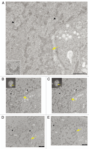
Figure 3 CLEM of a high pressure frozen, cryosubstituted and serially sectioned cell. (A) Anti-BMI1 immunogold labeling of heterochromatin structures (15 nm gold particles) of the same cell as in the Figure 2D, but a different thin section is shown in (A). The yellow arrow points to the nuclear region/domain that correlates with (the section of) the “PcG body” fluorescence seen in Figure 2B2 with the local density of heterochromatin structures being enriched in this domain. The heterochromatin structures are specifically enriched in the BMI1 immunogold label. Gold particles are sometimes situated towards the periphery of the heterochromatin structures (insert). (B–E) Four consecutive serial sections from the same area as shown in (A). In (B and C), the thin sections were first used for on-section immunofluorescence mapping of the BMI1 protein (inserts; note that the intensity of the “PcG body” in Fig. 3B is higher than that in Fig. 3C) to identify the position of the “PcG bodies”, and subsequently observed in the electron microscope (for a detailed analysis of the ultrastructural identification of the “PcG body”, see Sup. Figs. 3–5 in the Sup. Material). The two remaining serial thin sections (D and E) were on-section immunogold labeled for the BMI1 protein. Nucleolus (nu), cytoplasm (cy) and invaginagions of the nuclear envelope (black arrowheads) are designated in (A–E).
Supplemental material

Additional material

Download Zip (17.6 MB)