764
Views
3
CrossRef citations to date
0
Altmetric
RESEARCH PAPER

Identification of emergent motion compartments in the amniote embryo

, , , , , & show all
Pages 350-364 | Received 25 Jun 2014, Accepted 01 Sep 2014, Published online: 26 Jan 2015

Figures & data

Figure 1. Diagram explaining the method used for microsurgery and tissue culture on a microscope stage of explanted HH4-stage quail embryo tissue. A) Tissue explants were derived from three A/P positions: 1) Hensen's node (red), 2) anterolateral (orange) and 3) posterolateral (purple) epiblast. The extra-embryonic area opaca is shaded in light gray. B) A modified microsurgical pipette (pictured in C) was constructed from a common polyvinyl transfer pipet (TP) and a “P20” micropipette tip. The resulting device was prefilled with embryonic PBS, the tip was embedded into the epiblastic tissue at the locations indicated, and then using gentle suction the tissue of interest was excised (Hensen's node in this illustration). D) The explant was then placed, ventral surface up, onto a piece of vitelline membrane (cross-hatched green) that was previously attached to a Whatman paper ring (yellow circle). The paper ring preparation was transferred to a hydrated bed of albumin/agar (dark gray) contained in the well of a microscope stage tissue culture plate and then subjected to time-lapse imaging.
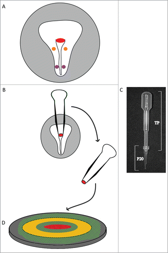
Figure 1. Diagram explaining the method used for microsurgery and tissue culture on a microscope stage of explanted HH4-stage quail embryo tissue. A) Tissue explants were derived from three A/P positions: 1) Hensen's node (red), 2) anterolateral (orange) and 3) posterolateral (purple) epiblast. The extra-embryonic area opaca is shaded in light gray. B) A modified microsurgical pipette (pictured in C) was constructed from a common polyvinyl transfer pipet (TP) and a “P20” micropipette tip. The resulting device was prefilled with embryonic PBS, the tip was embedded into the epiblastic tissue at the locations indicated, and then using gentle suction the tissue of interest was excised (Hensen's node in this illustration). D) The explant was then placed, ventral surface up, onto a piece of vitelline membrane (cross-hatched green) that was previously attached to a Whatman paper ring (yellow circle). The paper ring preparation was transferred to a hydrated bed of albumin/agar (dark gray) contained in the well of a microscope stage tissue culture plate and then subjected to time-lapse imaging.

Table 1. Summary of explant tissue behaviors observed in vitelline-membrane culture system

Figure 2. Early stages of avian gastrulation are characterized by morphogenetic movements that drive axis elongation. Panels A–F depict avian gastrulation (HH stages 4-7). The embryo undergoes a remarkable series of morphogenetic changes that underlie axis elongation. The red boxed region includes the midline axial structures that undergo tissue-scale elongation movements, indicated by a progressive reduction of width and increase in length, profiles A through F. In contrast to the elongating midline, the width of the lateral tissue (green brackets) remains relatively constant during gastrulation. Tracking of a small cluster of yolk particles (black arrow) serves as a reference point, which demonstrates the relative extension of tissue along the midline compared with the lateral tissue. Supplementary movie 1 accompanies . Mag bar = 100 μm.
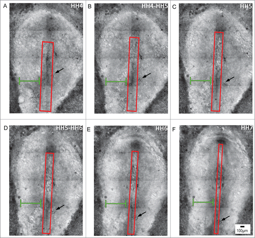
Figure 2. Early stages of avian gastrulation are characterized by morphogenetic movements that drive axis elongation. Panels A–F depict avian gastrulation (HH stages 4-7). The embryo undergoes a remarkable series of morphogenetic changes that underlie axis elongation. The red boxed region includes the midline axial structures that undergo tissue-scale elongation movements, indicated by a progressive reduction of width and increase in length, profiles A through F. In contrast to the elongating midline, the width of the lateral tissue (green brackets) remains relatively constant during gastrulation. Tracking of a small cluster of yolk particles (black arrow) serves as a reference point, which demonstrates the relative extension of tissue along the midline compared with the lateral tissue. Supplementary movie 1 accompanies figure 2. Mag bar = 100 μm.

Figure 3. Anterolateral and posterolateral epiblastic tissue explants demonstrate unpolarized (centrifugal) expansion during morphogenesis of the avian gastrula. A – F Tissue explants from the anterolateral epiblast undergo circumferential expansion during gastrulation. The initial perimeter tracing (white) is from HH4 embryonic tissue (A), and has been retained in all the profiles to denote the initial condition of the expanding tissue border. Tracings of the expanding front (orange) through HH7 (F) demonstrate the nearly concentric topology of the anterolateral tissue, suggesting its potential as an unpolarized morphogenetic movement generator. Supplementary movie 2 accompanies , A – F. Mag bar = 100 μm. G – L Tissue explants from the posterolateral epiblast also undergo centrifugal expansion during gastrulation. The initial perimeter tracing (white) is from HH4 embryonic tissue (G) and has been highlighted in all the profiles to denote the initial state of the expanding tissue front. Tracings of the expanding edge (purple) through HH stage 7 (L) demonstrates that the posterolateral tissue, similar to the anterolateral tissue, expands nearly concentrically during the stages (HH4 – HH7) that correspond to gastrulation of the early embryo. Supplementary movie 3 accompanies , (G – L). Mag bar = 100 μm.
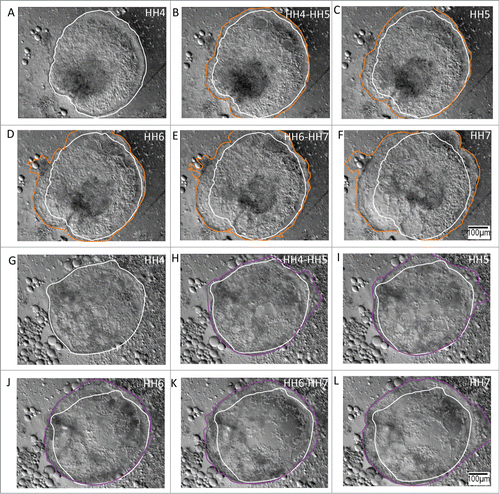
Figure 3. Anterolateral and posterolateral epiblastic tissue explants demonstrate unpolarized (centrifugal) expansion during morphogenesis of the avian gastrula. A – F Tissue explants from the anterolateral epiblast undergo circumferential expansion during gastrulation. The initial perimeter tracing (white) is from HH4 embryonic tissue (A), and has been retained in all the profiles to denote the initial condition of the expanding tissue border. Tracings of the expanding front (orange) through HH7 (F) demonstrate the nearly concentric topology of the anterolateral tissue, suggesting its potential as an unpolarized morphogenetic movement generator. Supplementary movie 2 accompanies figure 3, A – F. Mag bar = 100 μm. G – L Tissue explants from the posterolateral epiblast also undergo centrifugal expansion during gastrulation. The initial perimeter tracing (white) is from HH4 embryonic tissue (G) and has been highlighted in all the profiles to denote the initial state of the expanding tissue front. Tracings of the expanding edge (purple) through HH stage 7 (L) demonstrates that the posterolateral tissue, similar to the anterolateral tissue, expands nearly concentrically during the stages (HH4 – HH7) that correspond to gastrulation of the early embryo. Supplementary movie 3 accompanies figure 3, (G – L). Mag bar = 100 μm.

Figure 4. Tissue explants from Hensen's node (the avian organizer) demonstrate polarized expansion in culture, which is reminiscent of axis elongation. (A – F) The nearly circular initial perimeter (white trace) of the organizer explants from HH5 embryos fails to persist at the expanding tissue front through HH7. In contrast to anterolateral and posterolateral tissue explants, the node explants undergo a polarized extension reminiscent of notochord elongation in the intact embryo (red trace). Red and green arrows denote the convergence and extension boundaries of the tissue, respectively; thus, demonstrating that the Hensen's node tissue has the potential to act as a polarized morphogenetic movement generator. Supplementary movie 4 accompanies . Mag bar = 100 μm.
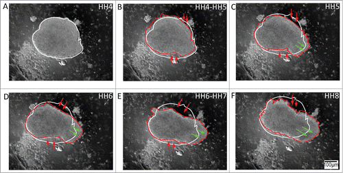
Figure 4. Tissue explants from Hensen's node (the avian organizer) demonstrate polarized expansion in culture, which is reminiscent of axis elongation. (A – F) The nearly circular initial perimeter (white trace) of the organizer explants from HH5 embryos fails to persist at the expanding tissue front through HH7. In contrast to anterolateral and posterolateral tissue explants, the node explants undergo a polarized extension reminiscent of notochord elongation in the intact embryo (red trace). Red and green arrows denote the convergence and extension boundaries of the tissue, respectively; thus, demonstrating that the Hensen's node tissue has the potential to act as a polarized morphogenetic movement generator. Supplementary movie 4 accompanies figure 4. Mag bar = 100 μm.

Figure 5. Both extracellular matrix (ECM) scaffold motion and cell autonomous motion characterize tissue-level morphogenetic movements in cultured explants. (A – F) Representative anterolateral tissue explant obtained from an embryo injected with fluorescent (Cy3) fibronectin antibody. Since fibronectin filaments are not self-propelled the fluorescence profiles demonstrate tissue dynamics as judged by passive ECM motion. In this way the anisotropic morphology of the expanding tissue could be distinguished by a relatively dense fibronectin network at the explant's core, yellow boundary trace, surrounded by a relatively sparse fluid-like boundary traced in blue. The time-lapse series demonstrates a circumferentially expanding fluid-like front, in which the peripheral expansion is accompanied by deformation of the ECM rich core region. Green arrows mark bundles of fibronectin that appear to extend between the dense ECM and sparse ECM regions. Supplementary movie 5 accompanies (A – F). Mag bar = 100 μm. (G – J) Representative Hensen's node tissue explant obtained from a transgenic quail bearing a ubiquitous H2B-mcherry nuclear marker (Lansford et al. manuscript in preparation). The time-lapse frames demonstrate collective cellular motion within the explants. The time-trace cell motility analysis (K) shows the cell populations at the circular explant periphery (blue/purple) driving the polarized tissue extension (red/orange), thus reaching the elongating ends of the explant (yellow/white) during the time period that corresponds to HH stages 4 through 8. Meanwhile, displacement vector analysis of a subpopulation of cells in the nodal explant (L) shows cellular convergence and extension motion patterns. Extension at the antero-posterior edges of the nodal tissue is particularly evident. Supplementary movie 6 accompanies (G – J). Heat-map depicts the elapsed time course. Mag bar = 100 μm.
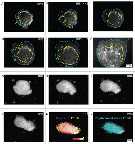
Figure 5. Both extracellular matrix (ECM) scaffold motion and cell autonomous motion characterize tissue-level morphogenetic movements in cultured explants. (A – F) Representative anterolateral tissue explant obtained from an embryo injected with fluorescent (Cy3) fibronectin antibody. Since fibronectin filaments are not self-propelled the fluorescence profiles demonstrate tissue dynamics as judged by passive ECM motion. In this way the anisotropic morphology of the expanding tissue could be distinguished by a relatively dense fibronectin network at the explant's core, yellow boundary trace, surrounded by a relatively sparse fluid-like boundary traced in blue. The time-lapse series demonstrates a circumferentially expanding fluid-like front, in which the peripheral expansion is accompanied by deformation of the ECM rich core region. Green arrows mark bundles of fibronectin that appear to extend between the dense ECM and sparse ECM regions. Supplementary movie 5 accompanies figure 5(A – F). Mag bar = 100 μm. (G – J) Representative Hensen's node tissue explant obtained from a transgenic quail bearing a ubiquitous H2B-mcherry nuclear marker (Lansford et al. manuscript in preparation). The time-lapse frames demonstrate collective cellular motion within the explants. The time-trace cell motility analysis (K) shows the cell populations at the circular explant periphery (blue/purple) driving the polarized tissue extension (red/orange), thus reaching the elongating ends of the explant (yellow/white) during the time period that corresponds to HH stages 4 through 8. Meanwhile, displacement vector analysis of a subpopulation of cells in the nodal explant (L) shows cellular convergence and extension motion patterns. Extension at the antero-posterior edges of the nodal tissue is particularly evident. Supplementary movie 6 accompanies figure 5(G – J). Heat-map depicts the elapsed time course. Mag bar = 100 μm.

Figure 6. Loss of lateral and nodal tissue regions compromises the morphogenetic movements during the generation of axial structures. A – C HH4 embryos allowed to develop after the removal of posterolateral epiblastic tissue (purple trace) generate extended axial structures (green and yellow profiles) despite significant expansion of the wounded area. Whereas, embryos deprived of nodal tissue fail to form recognizable axial structures (6D – 6F, red trace). Supplementary movies 7 & 8 accompany (A – C) and 6(D – F) respectively. Mag bar = 100 μm.
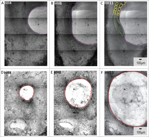
Figure 6. Loss of lateral and nodal tissue regions compromises the morphogenetic movements during the generation of axial structures. A – C HH4 embryos allowed to develop after the removal of posterolateral epiblastic tissue (purple trace) generate extended axial structures (green and yellow profiles) despite significant expansion of the wounded area. Whereas, embryos deprived of nodal tissue fail to form recognizable axial structures (6D – 6F, red trace). Supplementary movies 7 & 8 accompany figures 6(A – C) and 6(D – F) respectively. Mag bar = 100 μm.

Figure 7. Tissue-level kinematics of both lateral and nodal explants are dependent on intact rho-associated protein kinase (p160ROCK) signaling. Tissue explants fail to demonstrate morphogenetic movements when cultured in the presence of Y-27632, an inhibitor of ROCK signaling. The interference with actin polymerization and actomyosin contraction affects both lateral tissue and nodal explant morphogenetic movements. Circumferential expansion in the posterolateral explants (A – C, initial perimeter tracing in white) is diminished and is accompanied by a loss of tissue integrity and tearing (red arrows). The tissue expansion appears to be driven by loss of cell-cell contact and overall tissue disintegration. The treated explants from Hensen's node (D – F) fail to undergo their characteristic convergent extension movements, and also manifest a loss of tissue integrity (red arrows). Indeed, treatment of lateral and nodal explants results in termination of morphogenesis – compare the similar appearance of the final time points. Supplementary movies 9 & 10 accompany (A – C) and 7(D – F) respectively. Mag bar = 100 μm.
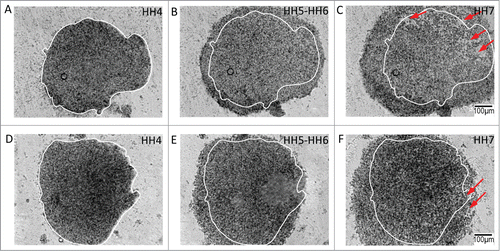
Figure 7. Tissue-level kinematics of both lateral and nodal explants are dependent on intact rho-associated protein kinase (p160ROCK) signaling. Tissue explants fail to demonstrate morphogenetic movements when cultured in the presence of Y-27632, an inhibitor of ROCK signaling. The interference with actin polymerization and actomyosin contraction affects both lateral tissue and nodal explant morphogenetic movements. Circumferential expansion in the posterolateral explants (A – C, initial perimeter tracing in white) is diminished and is accompanied by a loss of tissue integrity and tearing (red arrows). The tissue expansion appears to be driven by loss of cell-cell contact and overall tissue disintegration. The treated explants from Hensen's node (D – F) fail to undergo their characteristic convergent extension movements, and also manifest a loss of tissue integrity (red arrows). Indeed, treatment of lateral and nodal explants results in termination of morphogenesis – compare the similar appearance of the final time points. Supplementary movies 9 & 10 accompany figures 7(A – C) and 7(D – F) respectively. Mag bar = 100 μm.

Figure 8. Tissue flow-field analysis of morphogenetic movements in avian gastrula. Tissue flow-field analysis showing the velocity stream lines overlaid on divergence contour maps in the whole embryo at a representative time-lapse transition during the early (A), intermediate (B) and late (C) gastrula stages. Note the predominant divergent forces driving anteroposterior elongation of the embryo (B & C). Similar morphogenetic maps are shown for the anterolateral (D – F), posterolateral (G – I), and node (J – L) tissue explants. Foci of positive divergence (red, orange and yellow) propel expansion of lateral tissue at the periphery (F & I). Foci of convergence (blue) and divergence (red, orange and yellow) elongate the nodal explant (J – L). The white-out regions are areas where no reliable vectors could be computed. Zero values for divergence are indicated by dashed lines over the contour maps. Positive values for divergence on the heat maps signify locally expanding tissue flow within explants.
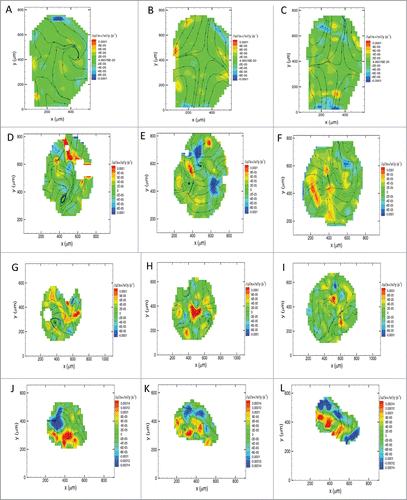
Figure 8. Tissue flow-field analysis of morphogenetic movements in avian gastrula. Tissue flow-field analysis showing the velocity stream lines overlaid on divergence contour maps in the whole embryo at a representative time-lapse transition during the early (A), intermediate (B) and late (C) gastrula stages. Note the predominant divergent forces driving anteroposterior elongation of the embryo (B & C). Similar morphogenetic maps are shown for the anterolateral (D – F), posterolateral (G – I), and node (J – L) tissue explants. Foci of positive divergence (red, orange and yellow) propel expansion of lateral tissue at the periphery (F & I). Foci of convergence (blue) and divergence (red, orange and yellow) elongate the nodal explant (J – L). The white-out regions are areas where no reliable vectors could be computed. Zero values for divergence are indicated by dashed lines over the contour maps. Positive values for divergence on the heat maps signify locally expanding tissue flow within explants.
Supplemental material

Supplemental_Material.zip

Download Zip (29.6 MB)

Reprints and Corporate Permissions

Please note: Selecting permissions does not provide access to the full text of the article, please see our help page How do I view content?

To request a reprint or corporate permissions for this article, please click on the relevant link below:

Academic Permissions

Please note: Selecting permissions does not provide access to the full text of the article, please see our help page How do I view content?

Obtain permissions instantly via Rightslink by clicking on the button below:

If you are unable to obtain permissions via Rightslink, please complete and submit this Permissions form. For more information, please visit our Permissions help page.