Figures & data
Figure 1. NO distribution in hypocotyl explants at different stages of adventitious rooting. Hypocotyl explants as visualized with MNIP-Cu treatment after 4 (A), 5 (B) and 7 (C) days of incubation in 10 µM of IAA in dark. Scale bar represents 2 mm.
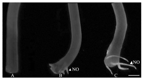
Figure 2. A. Effect of various physiological treatments on NO distribution in protoplasts isolated from the hypocotyls of 4 d old, light grown seedlings. (A−D) represent control protoplasts, (E−H) are treated with auxin (10 µM IAA). (I−L) are treated with auxin influx inhibitor (10 µM NPA) and (M−P) are treated with NO donor (100 µM SNP). After incubation in each treatment for 30 min, NO was localized using 25 µM MNIP-Cu and visualized at ex. 365 nm (em. 420 nm) (B, F, J and N). Co-incubation with 1 mM PTIO (D, H, L and P) confirmed the fluorescence due to NO. All the observations were taken at 630×. B. Relative fluorescence units data from protoplasts subjected to MNIP-Cu treatment for NO localization. Each datum represents mean value and standard errors from ten protoplasts subjected to a particular treatment.
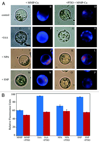
Figure 3. Localization of tyrosine nitrated proteins by CLSM imaging using anti-nitrotyrosine antibody. Visible and fluorescence micrographs of 10 µM thick hypocotyls sections from the basal regions of the explants subjected to treatment of PTIO (1.5 mM) (A-D), SNP (100 µM) + NPA (10 µM) (E-H), SNP (100 µM) + NPA (10 µM) (I-L) and SNP (100 µM) (M-P) in the presence of anti-nitrotyrosine antibody. (C, D, G, H, K, L, O and P): Maginified views (400×) of (A, B, E, F, I, J, M and N) (100×) respectively, show the differential distribution of tyrosine nitrated proteins in the vascular bundles.
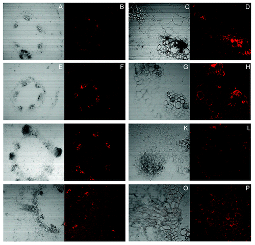
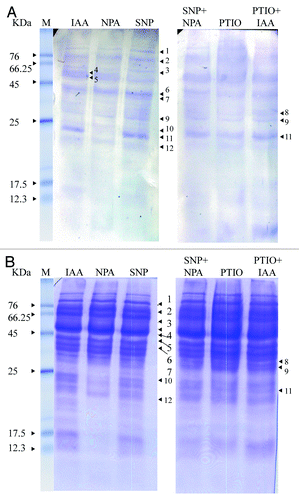
Figure 4. western blot analyses of anti-nitrotyrosine labeled proteins (A) and Coomassie stained gel images (B) of hypocotyl segments incubated in IAA (10 µM), NPA (10 µM), SNP (100 µM), SNP+NPA, PTIO (1 mM) and PTIO+IAA for seven days. Other details as in “Materials and Methods.” M, marker.