 ?Mathematical formulae have been encoded as MathML and are displayed in this HTML version using MathJax in order to improve their display. Uncheck the box to turn MathJax off. This feature requires Javascript. Click on a formula to zoom.
Abstract
The analysis of rectangular two-way slabs subjected to concentrated load uniformly distributed over defined area after dispersion down in the two directions to the reinforcement is a practically important case. As presented by Egyptian code for design and construction of concrete structures ECCS 203-2007, the analysis of this problem can be performed by using the elastic analysis or by using an approximate method which depends on the distribution of the concentrated load in the two directions by the ratio of the long length and short length of the rectangular slab. Significant differences between the results of these methods must take our attention. An alternative approximate method for determining the bending moments of the slab under study in the two directions is investigated in this paper based on the elastic analysis. Two closed-form expressions were obtained which describe the relation between the bending moments and all factors that affect it (the span ratio, the dimensions ratio of the loaded area and the ratio between the short span to the parallel length of the loaded area). Comparisons between the straining actions in the two directions resulting from the present analysis and these from the existing approximate method of the ECCS 203-2007 with those obtained by international codes as British Standards BS8110 and those obtained by finite element method are given also in this paper.
Introduction
When a slab is supported other than on two opposite sides only, the precise amount and distribution of the load taken by each support, and consequently the magnitude of the bending moments on the slab, are not easily calculated if assumptions resembling practical conditions are made. Therefore approximate analyses are generally used. The method applicable in any particular case depends on the shape of the panel of slab, the condition of restraint at supports, and the type of load.
Two basic methods [Citation1–Citation3] are commonly used to analyse slabs spanning in two directions. These are the theory of plates which is based on elastic analysis under service loads, and yield-line theory in which the behaviour of the slab as collapse approaches is considered. A less well-known alternative to the latter is Hillerborg’s strips method [Citation2,Citation4].
For rectangular panel carrying uniform load simply supported along all four edges and which no provision is made at the corners to prevent them lifting or to resist torsion, the Grashof and Rankine method [Citation4] is applicable. When the corners of the slab are prevented from lifting and torsional restraint is provided, the simple Grashof and Rankine method is inappropriate. A more exact elastic analysis, assuming a value of Poisson’s ratio, is performed and the resulting service bending moments at mid-span is given in tables for simplicity as used in most international codes [Citation5,Citation6].
| Nomenclature | ||
| Upper case Latin letters | = | |
| Mx, My | = | bending moments per unit length of sections of a plate perpendicular to x and y axes, respectively |
| E | = | Young’s modulus |
| P | = | concentrated load |
| Ln | = | natural logarithm |
| Lower case Latin letters | = | |
| (x, y) | = | rectangular coordinantes |
| t | = | slab thickness |
| d | = | slab depth |
| c | = | flooring thickness |
| Lower case Greek letters | = | |
| υ | = | Poisson’s ratio |
When a slab carries a load concentrated on a part only of the slab, such as a wheel load on the deck of a bridge, the contact area of the load is first extended by dispersion through the thickness of the slab and the flooring (if any). If the slab supported on two opposite sides only, the width of slab carrying the load may be assumed and the total concentrated load is then divided by this width to give the load carried on a unit width of slab for purpose of calculating the bending moments. For slabs spanning in two directions carrying a load uniformly distributed over a defined area on a part only of the slab, the British Standards BS8110 [Citation6] gives the bending moments on simply supported panel along all four sides with restrained corners by curves based on Pigweed’s theory but the Egyptian code ECCS 203-2007 [Citation7] presents an approximate method which depends on the distribution of the load in the two directions.
In this paper, our attention is, firstly, focused to the significant differences between the results of these methods and the comparison between these results and the finite element method. The results obtained from international codes such as British Standards BS8110 agreed with the results obtained by finite element method with good accuracy while the difference between the results of the ECCS 203-2007 and the finite element method is not acceptable.
Also in this paper, closed-form expressions are obtained using a theoretical analysis based on the theory of plates to determine the bending moments in the two directions directly as a function of the variables. A comparison of the results with finite element method [Citation8] is given in this thesis.
Model and assumptions
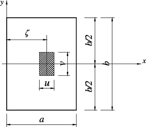
Consider a rectangular plate simply supported along all four edges as shown in , carrying a concentrated load (P) uniformly distributed over a defined area with the following assumptions:
| – | There is no deformation in the middle plane of the plate. This plane remains neutral during bending. | ||||
| – | The corners of the slab are prevented from lifting and torsional restraint is provided. | ||||
Fig. 1 Simply supported rectangular slab subjected to a concentrated load uniformly distributed over a defined area.
Review of egyptian code (eccs 203-2007) and british standards (bs 8110)
Egyptian Code (ECCS 203-2007)
As introduced in clause (6-2-1-5) of the Egyptian code for design and construction of concrete structures ECCS 203-2007, the concentrated load is considered to disperse down to a rectangular area with sides u and v which is determined from:(1)
(1) where t1 and t2 are the contact area of the concentrated load in directions perpendicular to and parallel to the main reinforcement, c is the flooring thickness and t is the slab thickness.
The concentrated load is distributed by an inverse ratio of the slab lengths according to these relations:(2)
(2)
To calculate the bending moment in direction (a), Pa is considered distributed on a length A of the effective span a and in a breadth B in the direction perpendicular to direction (a). in the contrary, the bending moment in direction, Pb is considered distributed on a length B of the effective span b and in a breadth A in the direction perpendicular to direction (b), where,(3)
(3)
British Standards (BS 8110)
The concentrated load is considered to disperse down to a rectangular area with sides u and v which are determined from:(4)
(4) where d is the slab depth.
The positive bending moments on unit width of slab are given by these expressions:(5)
(5) where values of αx4 and αy4 obtained by curves for the appropriate value of the spans ratio (r = b/a) corresponding to the ratios u/a and v/b.
Method of analysis and theoretical equations
The bending moments of the slab spanning in two directions carrying concentrated load uniformly distributed over a rectangular area is obtained in [Citation1] using Navier’s method by the following expressions:(6)
(6)
(7)
(7)
In which,
In order to derive simple expressions to determine bending moments, we let (ξ = a/2) where the maximum bending moments and by some arrangements, the bending moment in the short direction Mx can be put in the following form:(8)
(8) where
.
Putting,(9)
(9)
And using the known series:(10)
(10)
The terms λ and μ can be expressed
as:(11)
(11)
(12)
(12)
The terms λ and μ are wholly independent of dimensions of u and v of loaded area where these are function in spans ratio r only. In the contrary, the values of factors ϕ and ψ are depending only on the ratio v/u. Substituting Eqs. (Equation11(11)
(11) ) and (Equation12
(12)
(12) ) into Eq. (Equation6
(6)
(6) ), the terms (λ + μ), (λ − μ), (ψ + ϕ), and (ψ − ϕ) can be put in simple expressions as:
(13)
(13)
Substituting Eq. (Equation13(13)
(13) ) into Eq. (Equation8
(8)
(8) ), and assuming Poisson’s ratio υ = 0.20 which is recommended by ECCS 203-2007 and other international codes as BS 8110, the bending moment Mx can be expressed as:
(14)
(14)
(15)
(15)
Eq. (Equation14(14)
(14) ) can be expressed in simple expression as follows:
(16)
(16)
In a similar manner, we get the bending moment in the long direction My as follows:(17)
(17)
Illustrative examples
To describe the problem considered in this paper and to clarify applying of the obtained equations in the present work, two numerical examples are given which are solved by the approximate method introduced in ECCS203-2007, British standards BS 8110 and the present work. Also, the two examples are solved by Finite element method [Citation8] to check the accuracy of each one of the previous methods,
Example 1: A square slab of 3.0 m side simply supported on all four sides, subjected to a concentrated load 200 kN symmetrically placed at the centre of the panel. Contact area being 75 mm by 600 mm. The slab thickness is 200 mm (d = 175 mm) and the flooring is 50 mm thickness.
Using ECCS 203-2007: the sides of the loaded area after the load disperses down to the reinforcement (u, v) are:
u = 75 + 2 × 50 + 200 = 375 mm, and v = 600 + 2 × 50 + 200 = 900 mm
The loads distributed in each direction are:
Pa = 200 × 3/(3 + 3) = 100 kN, and Pb = 100 kN
Pa is distributed on a length A of the effective span a and in a breadth B in the direction perpendicular to direction a where,
A = 0.375 + 0.4 × 3.00 = 1.575 m, and B = 0.9 + 0.4 × 3[2 − 3/3] = 2.10 m
Thus, the service bending moments per metre width are:
Mx = 26.34 kN m/m
My = 30.95 kN m/m
The sides of the loaded area (u, v) are
u = 75 + 2 × 50 + 2 × 175 = 525 mm, and v = 600 + 2 × 50 + 2 × 175 = 1050 mm
r = 3.0/3.0 = 1.0
From the appropriate curve (r = 1.0) and corresponding to u/a = 0.525/3.0 = 0.175, and v/b = 1.05/3 = 0.35 the coefficient αx4 and αy4 are obtained as:
αx4 = 0.16 and αy4 = 0.13
Thus,
Mx = 200(0.16 + 0.2 × 0.13) = 37.20 kN m/m,
My = 200(0.16 × 0.2 + 0.13) = 32.40 kN m/m
Using present work:
The sides of the loaded area (u, v) are:
u = 75 + 2 × 50 + 2 × 175 = 525 mm, and v = 600 + 2 × 50 + 2 × 175 = 1050 mm
r = 3.0/3.0 = 1.0, k = v/u = 1.05/.525 = 2.0, and k1 = a/u = 3.0/0.525 = 5.714
Substituting in Eqs. (Equation16(16)
(16) ), (Equation17
(17)
(17) ):
Using F.E.M.:
Mx = 36.64 kN m/m,
My = 32.22 kN m/m
Example 2: Consider a rectangular slab which is 3.75 m long by 3.0 m wide simply supported on all four sides, subjected to the same load and assuming the same assumptions given in the previous example.
Using ECCS 203-2007:
u = 75 + 2 × 50 + 200 = 375 mm, and v = 600 + 2 × 50 + 200 = 900 mm
Pa = 200 × 3.75/(3 + 3.75) = 111.11 kN, and Pb = 88.89 kN
A = 0.375 + 0.4 × 3.00 = 1.575 m, and B = 0.9 + 0.4 × 3[2 − 3/3.75] = 2.34 m
Thus,
Mx = 26.26 kN m/m
My = 25.82 kN m/m
Using BS8110:
u = 75 + 2 × 50 + 2 × 175 = 525 mm, v = 600 + 2 × 50 + 2 × 175 = 1050 mm and r = 3.75/3.0 = 1.25
From the appropriate curve (r = 1.25) and corresponding to u/a = 0.525/3.0 = 0.175, and v/b = 1.05/3 = 0.35, the coefficient αx4 and αy4 are obtained as αx4 = 0.19 and αy4 = 0.12
Thus,
Mx = 200 (0.19 + 0.2 × 0.12) = 42.80 kN m/m,
My = 200 (0.19 × 0.2 + 0.12) = 31.60 kN m/m
Using present work:
r = 3.75/3.0 = 1.25, k = v/u = 1.05/.525 = 2.0, and k1 = a/u = 3.0/0.525 = 5.714
Substituting in Eqs. (Equation16(16)
(16) ), (Equation17
(17)
(17) )
Mx = 40.23 kN m/m,
My = 30.78 kN m/m
Using F.E.M.:
Mx = 40.74 kN m/m,
My = 31.48 kN m/m
Comparison of the results
From the results of the previous two examples, shows the comparison of the bending moments obtained by Eqs. (Equation16(16)
(16) ), (Equation17
(17)
(17) ) of the present work (P.W.), the approximate method given in clause (6-2-1-5) of the ECCS 203-2007 and the British standards BS8110 with the results obtained by elastic analysis as programmed by finite element method [Citation8].
Table 1 Comparison of Mx and My obtained by P. W., ECCS 203-2007 and BS 8110 with F.E.M. [Citation8].
It can be noticed that although the present equations are simple, it gave more accurate results when compared with the solution by finite element method. Then, the present equations can be rather used by the designer engineers.
Conclusions
In this paper, a theoretical analysis based on the elastic analysis is developed to determine the service bending moments of the slab spanning in two directions carrying a concentrated load uniformly distributed over a defined area on a part only of the slab. From results and examples carried out in this paper, the following conclusions are drawn:
| (1) | Significant differences between the results of the approximate method introduced in clause (6-2-1-5) of the Egyptian code for design and construction of concrete structures ECCS 203-2007 and the elastic solution e.g. by finite element method. Also, significant differences between the results of ECCS 203-2007 and that obtained by other international codes as the British Standards BS8110. These differences are large enough to consider the approximate method introduced in ECCS 203-2007 to be unsafe. | ||||
| (2) | The present analysis describes the relation between the bending moments and all the factors that affect it which are the span ratio, the dimensions ratio of the loaded area and the ratio between the short span to the parallel length of the loaded area (represented by factors r, k and k1 respectively). | ||||
The great advantage of the present analysis is the determination of the bending moments by using hand calculations only (without the use of curves or tables). Two numerical examples demonstrated the use of the obtained equations for slabs under study and comparing the results with British Standards BS8110 [Citation4,Citation6] as well as the finite element method, as programmed in SAP2000 [Citation8].
Finally, the present analysis provides relatively simple two expressions from which the bending moments for slabs under study can be easily calculated. These equations can be of great help for design purposes. The comparison of the results with the finite element method confirms the accuracy of such equations.
Notes
Peer review under responsibility of Housing and Building National Research Center.
References
- TimoshenkoS.WoinowskyTheory of Plates and Shells1987McGraw-Hill Book CompanyLondon
- R.SzilardTheories and Applications of Plate Analysis: Classical, Numerical and Engineering Methods2004John Wiley & Sons, Inc.New Jersey, Hoboken
- J.Y.RichardN.E.ShanmuganHandbook of Structural Engineering2005CRC press
- C.E.ReynoldsJ.C.SteedmanA.J.ThrelfallReynolds’s Reinforced Concrete Designer’s HandbookEleventh ed.2008Taylor & Francis GroupLondon, New York
- ACI Committee 318Building Code Requirements for Structural Concrete (ACI 318–95) and Commentary (ACI 318 R-95)1995American Code InstituteMichigan, Farmington Hills
- BS8110. Structural Use of Concrete, British Standard Institution, 1985.
- Housing and Building Research Centre. Egyptian Code for Design and Construction of Concrete Structures. Code No. (203), Ministerial Decree No. 44–2007, Ministry of Housing, Utilities and Urban, Communities, 2007.
- Sap 2000Advanced 14.1.0.Computer Software for Static and Dynamics Finite Element Analysis of Structures2009Computer & Structures Inc.Berkely, California, USA