
 ?Mathematical formulae have been encoded as MathML and are displayed in this HTML version using MathJax in order to improve their display. Uncheck the box to turn MathJax off. This feature requires Javascript. Click on a formula to zoom.
Abstract
In this paper, a comparison study has been carried out between the limit equilibrium (conventional) methods and finite element method of estimation factor of safety of slopes under the effect of rainfall. A case study is analyzed with the finite element method, and the results are compared with outcomes from some of the well-known conventional methods namely: simplified Bishop Method (1955), simplified Janbu method (1954), and Fellenius method (1927).
Moreover, slope stability concerning rainfall and infiltration is analyzed. Specially, two kinds of infiltrations (saturated and unsaturated) are considered. Many slopes become saturated during periods of intense rainfall or snowmelt, with the water table rising to the ground surface, and water flowing essentially parallel to the direction of the “slope” and “Influence” of the change in shear strength, density, pore-water pressure and seepage force in soil slices on the slope stability is explained. Finally, it is found that classical limit equilibrium methods are highly conservative compared to the finite element approach. For assessment the factor of safety for slope using the later technique, no assumption needs to be made in advance about the shape or location of the failure surface, slice side forces and their directions. This document outlines the capabilities of the finite element method in the analysis of slope stability problems.
Introduction
In most applications, the primary purpose of slope stability analysis is to contribute to the safe and economic design of excavations, embankments, earth dams, landfills, and spoil heaps. Several methods for calculating safety factors of slopes have been published in the literature. A detailed review of equilibrium methods of slope stability analysis is presented by Duncan [Citation4] .These methods include the ordinary method of slices, Bishop’s modified method, force equilibrium methods, Janbu’s generalized procedure of Slices, Morgenstern and Price’s method and Spencer’s method. These methods, in general, require the soil mass to be divided into slices. The directions of the forces acting on each slice in the slope are assumed. This assumption has a key role in distinguishing one limit equilibrium method from another.
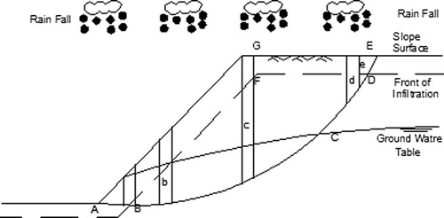
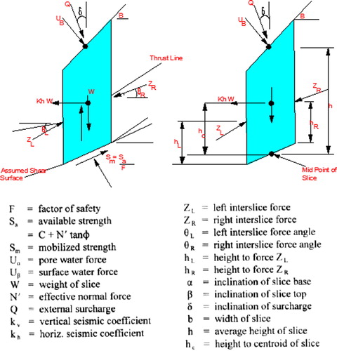
illustrates the effect of rainfall on slope stability. Rainfall induces changes of soil behavior, which mainly include: the increase of volumetric water content (θ), saturation degree (Sr), coefficient of permeability (k) and bulk density (γ); the decrease of effective cohesion (C) and internal degree of friction (φ), the decrease or even disappearance of matrix suction (sa) and the appearance and increase of pore-water pressure (u) Xiong et al. [Citation5] and Hu et al. [Citation6], and the development of new strain and displacement in the slope Qi and Huang [Citation7]. Therefore the decrease of C, φ and sa on the slip surface, the increase of γ in slope and u on the slip surface during rainfall infiltration can cause the decrease of slope stability.
Fig. 1 State of slope under rainfall.
Saturation of a soil will decrease the frictional shear strength. This is due to the buoyant reduction in normal force required for frictional shear strength by the pore pressure (the effective stress principle). Saturation of soil may also destroy capillarity and “apparent cohesion” on the cohesive component of the soil, or may reduce the dry strength of a cohesive soil.
In the last few decades, finite element method has been increasingly used in slope stability analysis. The advantage of a finite element approach in the analysis of slope stability problems over traditional limit equilibrium methods is that no assumption needs to be made in advance about the shape or location of the failure surface, slice side forces and their directions. The method can be applied with complex slope configurations and soil deposits in two or three dimensions to model virtually all types of mechanisms. General soil material models that include the Mohr–Coulomb model and numerous others can be employed. The equilibrium stresses, strains, and the associated shear strengths in the soil mass can be computed very accurately. The critical failure mechanism developed can be extremely general and need not be simple circular or logarithmic spiral arcs Griffiths and Lane [Citation8].
In this paper, the main work focuses on two types of infiltration pattern (saturated and unsaturated), the two types of failure modes (shallow and deep-seated failure) and the four ways of affecting slope stability in the rainfall (the decrease of soil shear strength, the increase of bulk density, the increase of pore pressure and the action of seepage force). Besides, a comparison study is conducted between limit equilibrium (traditional) and finite element methods for prediction of factor of safety for slopes under heavy rainfall. Three conventional methods based on the concept of slices are used namely: simplified Bishop Method [Citation1], simplified Janbu method [Citation2], and Fellenius method [Citation3].
Behavior of slopes under effect of heavy rainfall
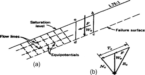
Many slopes become saturated during periods of intense rainfall or snowmelt, with the water table rising to the ground surface, and water flowing essentially parallel to the direction of the slope. Under this condition, soil element (abcd) in the infinite slope has the submerged weight W0 and the seepage force F acting as shown in . Using the hydraulic gradient method, the seepage force F can be determined from the flow net. This seepage force F acts as a driving force in the soil mass and hence can greatly lower the stability of the slope.
Fig. 2 Stress conditions in infinite slope with seepage parallel to the slope. (a) Diagram of slope. (b) Force polygon. (Cedergren [Citation9]).
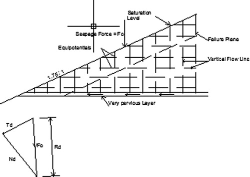
Cedergren [Citation9] showed that slopes can be fully saturated, but at the same time free of excess pore pressures and damaging seepage forces. This is the case when the slope is underlain by a highly pervious gravel layer (), where the flow net consists of vertical flow lines and horizontal equipotential.
Fig. 3 Stress conditions in infinite slope with vertical seepage. (a) Cross section. (b) Force polygon. (Cedergren [Citation9]).
Methods of evaluating safety factor for slopes under rainfall action
Limit equilibrium methods
Those methods are usually analyzed by discretizing the mass of the failure slope into smaller slices and treating each individual slice as a unique sliding block. All limit equilibrium methods of slope stability analysis divide a slide-mass into n smaller slices, as shown in . Each slice is affected by a general system of forces, as shown in . Three methods, which are based mainly on methods of slices, are used.
Fig. 4 Division of potential sliding mass into slices.
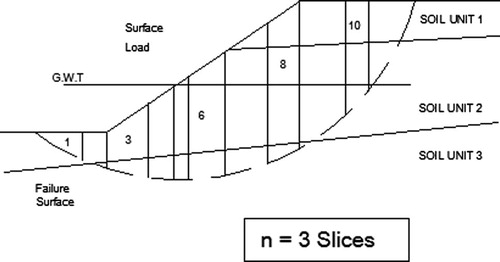
Fig. 5 Forces acting on a typical slice.
Simplified Bishop Method
This method satisfies vertical force equilibrium for each slice and overall moment equilibrium about the center of the circular trial surface. The simplified Bishop method also assumes zero interslice shear forces.
Thus, Bishop’s method could be used to compute a factor of safety (FOS) = F for noncircular surfaces, where FOS is factor of safety = “F” and can be calculated as follows:-(1)
(1) where:
(2)
(2)
(3)
(3)
(4)
(4) R = the resistance force
Simplified Janbu Method
The simplified janbu procedure assumes that there are no interslice shear forces. The geometry of each slice is described by its height, h, measured along its centerline, its width, b, and by the inclinations of its base and top, respectively. Janbu’s method satisfies vertical force equilibrium for each slice, as well as overall horizontal force equilibrium for the entire slide mass (i.e., all slices). Vertical force equilibrium for each slice is given by:(5)
(5) The above equation may be arranged for N′ as
(6)
(6) If the FOS against shear failure is defined as F, and is assumed to be the same for all slices, the Mohr–Coulomb mobilized shear strength, Sm, along the base of each slice is given by,
(7)
(7) where C and N′ tan φ are the cohesive and frictional shear strength components of the soil. The effective normal force acting at the base of the slice can be determined by
(8)
(8) where
(9)
(9) Next, the overall horizontal force equilibrium is evaluated for all slices of the slide mass. In this case,
(10)
(10) By rearranging the above equation, the following expression may be obtained:
(11)
(11) Then if each slice has the same FOS, F,
(12)
(12) where A4 = Resistance Factor.
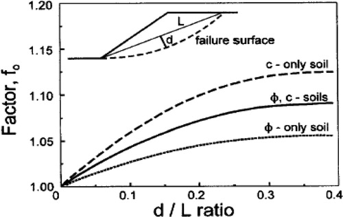
The reported Janbu factor of safety (F) value is calculated by multiplying the calculated F value by a modification factor, fo, .(13)
(13) This modification factor is a function of the slide geometry and the strength parameters of the soil. illustrates the variation of the fo value as a function of the slope geometry (i.e., d and L) and the type of soil. These curves were presented by Janbu in an attempt to compensate for the assumption of negligible interslice shear forces (Z sin α) in his formulation for the simplified method. Janbu then performed calculations using his simplified and rigorous (i.e., satisfying complete equilibrium) methods for the same slopes with homogeneous soil conditions. The subsequent comparison between the simplified and rigorous FOS values was used to develop the correction curves shown in .There is no consensus concerning the selection of the appropriate value for a surface intersecting different soil types consisting of C only, φ only, or both C and φ soils. In cases where such a mixed variety of soils is present, the c-curve is generally used to correct the calculated FOS value. For convenience, this modification factor can also be calculated according to the formula:
(14)
(14) where b1 varies according to the soil type: C only soil: b1 = 0.69, Ø only soil: b1 = 0.31, C and Ø soil: b1 = 0.50.
Fig. 6 Janbu’s correction factor for the simplified method.
Fellimens Method
In this method, landslide type is assumed rotational slip, as shown in . Moreover, landslide soil is divided into some slices in order to calculate moment along the critical circle. Therefore, some parameters shall be calculated as follows: R is radius of critical circle (m); W is weight of each slice (kN); α is angle between horizontal axis and the base of slice (degree); L is length of the base of slice (m); C is Cohesion (kN/m2); and φ is angle of shearing resistance (degree).
Fig. 7 Illustration of Fellenius method.
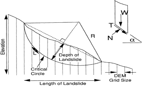
Factor of safety (F) can be estimated by the following formula:(15)
(15) where: ΣT is summation of driving moment, and ΣN is summation of resisting moment. shows N, T as force
(16)
(16)
(17)
(17)
Finite Element Method
Generally, there are two approaches to analyze slope stability using finite element method. One approach is to increase the gravity load and the second approach is to reduce the strength characteristics of the soil mass. The second approach is adopted in this study by using a powerful software finite element program called PLAXIS.
Material model, soil properties and model dimensions
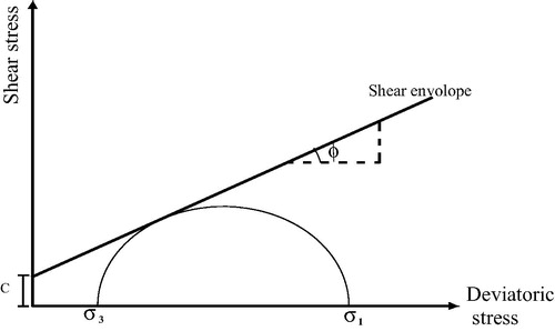
This work is applicable only for two-dimensional plane-strain problems. The Mohr–Coulomb constitutive model is used to describe the soil (or rock) material properties. The Mohr–Coulomb criterion relates the shear strength of the material to the cohesion, normal stress and angle of internal friction of the material.
Therefore, the Mohr–Coulomb model is adopted in this paper to model the behavior of soils. The mathematical expression of this model, as well known, is given by the following formula:(18)
(18) where: τ = shear strength of soil material on a certain failure plane, σn = normal stress on the failure plane, φ = angel of internal friction of soil material, and C = cohesion intercept of soil material.
The Mohr–Coulomb failure criterion in its simplest two-dimensional form consists of a linear envelope touching all Mohr’s circles representing combination of principal stresses at failure, as shown in .
Fig. 8 The Mohr–Coulomb failure criterion.
The Mohr–Coulomb model requires a total of five parameters, which are generally familiar to most geotechnical engineers and which can be obtained from basic tests on soil samples and in situ tests. Besides the plasticity parameters (C, Ф, and ψ), input requires two additional elastic parameters (E and υ). All parameters required by Mohr–Coulomb model are listed in .
Table 1 Parameters of the Mohr–Coulomb model.
α-C-reduction approach
In the design of an embankment it is important to consider not only the final stability, but also the stability during the construction.
It is interesting to evaluate a global safety factor at this stage of the problem, and also for other stages of construction.
In structural engineering, the safety factor is usually defined as the ratio of the collapse load to the working load. For soil structures, however, this definition is not always useful. For embankments, for example, most of the loading is caused by soil weight and an increase in soil weight would not necessarily lead to collapse. Indeed, a slope of purely frictional soil will not fail in a test in which the self weight of the soil is increased (like in a centrifuge test). A more appropriate definition of the factor of safety is therefore:where S represents the shear strength. The ratio of the true strength to the computed minimum strength required for equilibrium is the safety factor that is conventionally used in soil mechanics. By introducing the standard coulomb condition, the safety factor is obtained:
where c and φ are the input strength parameters and σn is the actual normal stress component. The parameters cr and σr reduced strength parameters that are just large enough to maintain equilibrium. The principle described above is the basis of the method of phi-c-reduction that can be used in PLAXIS to calculate a global safety factor. In this approach the cohesion and the tangent of the friction angle are reduced in the same proportion:
The reduction of strength parameters is controlled by the total multiplier ΣMsf. This parameter is increased in a step-by-step procedure until failure occurs. The safety factor is then defined as the value of ΣMsf at failure. Provided that at failure a more or less constant value is obtained for a number of successive load steps.
The phi-c-reduction calculation option is available in PLAXIS from the Calculation type list box on the General tab sheet. If the Phi-c-reduction option is selected the Loading input on the parameters tab sheet is automatically set to Incremental multipliers.
To calculate the global safety factor for the road embankment at different stages of construction, follow these steps:
Click on the Go to calculations program button to focus the Calculations window.
We first want to calculate the safety factor after the first construction stage. Therefore introduce a new calculation phase and select Phase 1 in the start from phase list box.
In the General tab sheet, select a Phi-c-reduction calculation.
In the Parameters tab sheet the number of Additional steps is automatically set to 100 (instead of the default value of 250). In order to exclude existing deformations from the resulting failure mechanism, select the Reset displacements to zero option. The Incremental multipliers option is already selected in the Loading input box. Click on the <Define> button to enter the Multipliers tab sheet.
In the Multipliers window, check that the first increment of the multiplier that controls the strength reduction process, Msf, is set to 0.1. The first safety calculation has now been defined.
In this approach the cohesion and the tangent of the friction angle are reduced in the same proportion, as follows (Dawson et al. [Citation10], Griffith and Lane [Citation8], Hammah et al. [Citation11]).
represents the dimensions and the boundary conditions of the finite element model. Factor of safety (F) according to Mohr–Coulomb is given by Plaxis manual [Citation12].
Fig. 9 Dimensions and boundary conditions of finite element model.
Case history
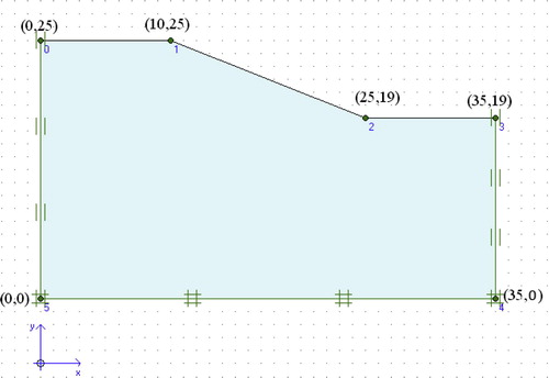
This case study of a slope subjected to a heavy rainfall is presented by Xiao-dong et al. [Citation13]. shows the profile of slope used in the study. gives the soil parameters for two cases (saturated and un-saturated slopes).
Fig. 10 Profile of slope in case study.
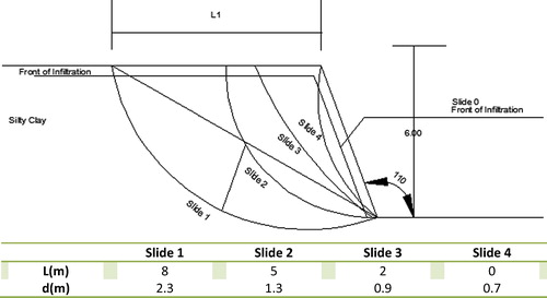
Table 2 Parameters used in the case study.
Analysis of results
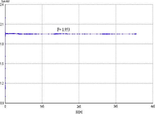
and show the results of total displacement increments for un-saturated and saturated slope obtained from finite element analysis, respectively. It is obvious that displacement increments for un-saturated slope are much higher than the saturated one. Besides, and illustrate the results of safety factors for un-saturated and saturated slope obtained from finite element analysis, respectively. The un-saturated slope gives safety factor of 2.547, while the saturated slope gives lower safety factor of 1.953.
Fig. 11 Shading of the total displacement increments for un-saturated case using finite element program Plaxis.
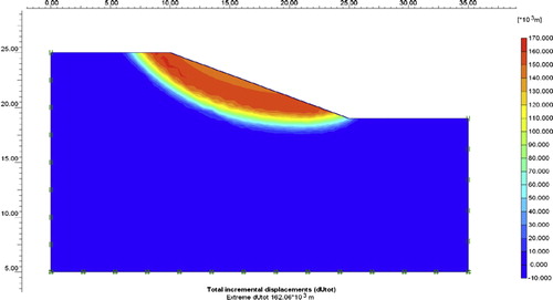
Fig. 12 Shading of the total displacement increments for saturated case using finite element program Plaxis.
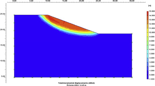
Fig. 13 Evaluation of safety factor for un-saturated case using finite element program Plaxis.
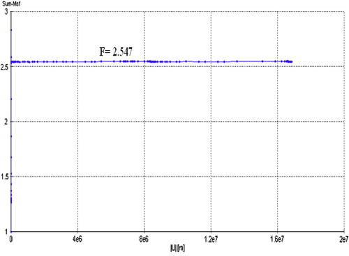
Fig. 14 Evaluation of safety factor for saturated case using finite element program Plaxis.
The results of safety factors obtained from limit equilibrium (traditional) methods are listed in . It can be seen that the limit equilibrium methods namely: simplified Bishop Method [Citation1], simplified Janbu method [Citation2], and Fellenius method [Citation3] give low value for the safety factors for saturated and unsaturated slopes. On the other hand, finite element method gives high safety factors for saturated and unsaturated slopes compared to the methods which are based on limit equilibrium concept.
Table 3 Summary of results for factor of safety.
Moreover, there is no wide variation in the factors of safety calculated using classical limit equilibrium methods because they are assessed based on the same concept.
However, there is a wide discrepancy between the conventional and finite element methods in assessment safety factors, and this may be attributed to one of the following reasons:
Classical limit equilibrium methods depend on the directions of the forces acting on each slice in the slope are assumed;
In finite element approach, the factor of safety emerges naturally from analysis without the user having to commit to any particular form of mechanism a priori;
Limit equilibrium methods require a continuous surface passing the soil mass. This surface is essential in calculating the minimum factor of safety (FOS) against sliding or shear failure.
Summary and conclusion
This paper represents a comparison study between finite element method using shear strength reduction approach and most widely used limit-equilibrium methods namely: simplified Bishop method [Citation1], simplified Janbu method [Citation2], and Fellenius method [Citation3]. The main conclusion is that classical limit equilibrium methods are highly conservative compared to the finite element approach. For assessment of the factor of safety for slope using the later technique, no assumption needs to be made in advance about the shape or location of the failure surface, slice side forces and their directions.
Notes
Peer review under responsibility of Housing and Building National Research Center.
References
- A.W.BishopThe use of slip circle in the stability analysis of slopesGeotechnique51955717
- N.JanbuApplication of composite slip surfaces for stability analysisProc. Eur. Conf. Stabil. Earth Slopes, Stockholm319544349
- W.Fellenius“Erdstatische Berechnungen mit Reibung und Koha” sion (Adha¨sion) und unter Annahme kreiszylindrischer Gleitfla¨chen1927Ernst & SohnBerlin
- J.M.DuncanState of the art: limit equilibrium and finite-element analysis of slopesJ. Geotech. Eng., ASCE12271996577597
- G.C.XiongY.F.RuanJ.YangAnalysis on relation between rainfall and slope stabilityUnderground Space17200510171020
- M.J.HuR.WangP.C.ZhangPrimary research on the effect of rainfall on landslide – take the slope piled by old landslide in Jiangjiagou valley as exampleChinese J. Geotech. Eng.2342001454457
- G.Q.QiR.Q.HuangStudy on slope displacements due to rainfallRock Soil Mech. (Chinese)2532004379382
- D.V.GriffithsP.A.LaneSlope stability analysis by finite elementsGeotechnique4931999387403
- H.CedergrenSeepage, Drainage, and Flow Netssecond ed.1977John Wiley and SonsNew York
- E.M.DawsonW.H.RothA.DrescherSlope stability analysis by strength reductionGeotechnique4961999835840
- R.E. Hammah, J.H. Curran, T.E. Yacoub, B. Corkum, (2004). “Stability Analysis Of Rock Slopes Using the Finite Element Method”. In Proceedings of the ISRM Regional Symposium EUROCK 2004 and the 53rd Geomechanics Colloquy, Salzburg, Austria.
- Plaxis Version 8.0, Tutorial manual.
- C.Xiao-dongG.Hong-xianS.Er-xiangAnalysis method for slope stability under rainfall actionChenLandslides and Engineered Slopes2008Taylor & Francis GroupLondon15071515