
 ?Mathematical formulae have been encoded as MathML and are displayed in this HTML version using MathJax in order to improve their display. Uncheck the box to turn MathJax off. This feature requires Javascript. Click on a formula to zoom.
Abstract
In most current codes of design steel members and frames, specifications for the design of compression columns or of beam-column use the effective length factor; K. The effective length factor is employed to facilitate the design of framed members by transforming an end-restrained compressive member to an equivalent pinned-ended member. The effective length factor is obtained by solving the exact equations numerically which require many routine calculations or by using a pair of alignment charts for the two cases of braced frames and sway frames. The accuracy of these charts depends on the size of the chart and the reader’s sharpness of vision. Instead of using complicated equations or charts, simple equations are required to determine the effective length factor directly as a function of the rotational resistant at column ends (GA, GB). In this paper, new simple and accurate equations for effective length factors are presented using multiple regressions for tabulated exact values corresponding to different practical values of the rotational resistance at column ends (GA, GB). The investigated equations are more accurate than equations that are recommended in some steel constructions codes. Comparisons between the results of the present equations and those obtained by equations presented in previous researches with those obtained by exact solutions are also given in this paper.
Introduction
The design of a column or of a beam-column starts with the evaluation of the elastic rotational resistance at both ends of the column (GA, GB), from which the effective length factor (K) is determined. The mathematically exact equations for braced and sway rigid frames were given by Barakat and chen [Citation6]. These equations require many routine calculations, and it is well suited for tedious column and beam-column calculations. The other way to determine the effective length factor (K) is the using of a pair of alignment charts for braced frames and sway frames, which were originally developed by O.J. Julian and L.S. Lawrence, and presented in detail by T.C. Kavanagh [Citation8]. These charts are the graphic solutions of the mathematically exact equations and these are commonly used in most codes as the manual of American institute of steel construction (LRFD and ASD) [Citation1,Citation2] and the Egyptian code of practice for steel constructions (LRFD and ASD) [Citation4,Citation5]. The accuracy of the alignment charts depends essentially on the size of the chart and on the reader’s sharpness of vision. Also, having to read K-factors from an alignment chart in the middle of an electronic computation, in spreadsheet for instance prevents full automation and can be a source of errors.
Obviously, it would be convenient to have simple equations take the place of the charts which are commonly used in most codes of steel constructions. The American Institute does publish equations but their lack of accuracy may be why they seem not to be used in steel design. Better equations have been available in the French design rule for steel structures since 1966, and have been included in the European recommendations of 1978 [Citation3] are presented by Pierre Dumonteil [Citation7].
In this paper, more accurate closed form equations for the determination of the effective length factors as a function of the rotational resistance at column ends are presented which are simple enough to be easily programed within the confines of spreadsheet cell. For this reason, they may be useful to design engineers.
Background to exact and approximate equations
Consider a column AB elastically restrained at both ends. The rotational restraint at one end, A for instance, is presented by restraint factor GA, expressing the relative stiffness of all the columns connected at A to that of all the beams framing into A:(1)
(1)
In the European Recommendation, another two factors βA and βB are used (rather than GA and GB as in French Rules). The definition of β differs from that of G, since, at each column end.(2)
(2) The mathematical relation between G and β is simple:
(3)
(3)
Europeans tend to prefer β to G because a hinge means β = 0 and fixity means β = 1. Obviously, the K-factor will be the same if the same elements are introduced in G and β.
Braced frames
Braced frames are frames in which the side sway is effectively prevented as shown in (a), and, therefore, the K-factor is never greater than 1.0. The side sway prevented alignment chart is the graphic solution of the following mathematical equation:(4)
(4)
Fig. 1 Braced and sway frames.
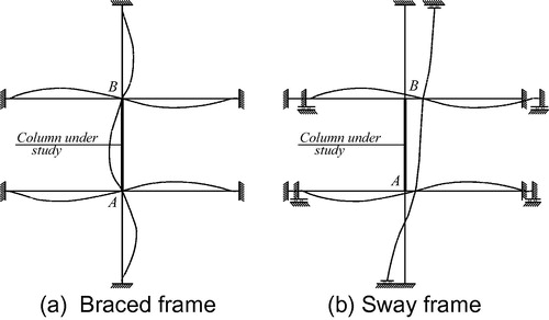
This equation is mathematically exact, in that certain physical assumptions are exactly translated into mathematical terms. Whether these assumptions can be reasonably extended to a specific structure is a matter for the designer to decide.
For the transcendental Eq. (Equation4(4)
(4) ), which can only be solved by numerical methods, the French Rules propose the following approximate solution:
(5)
(5)
Sway frames
If a rigid frame depends solely on frame action to resist lateral forces, its side sway is permitted as shown in (b). In this case, the K-factor is never smaller than 1.0. The mathematical equation for the permitted sway case is:(6)
(6)
Although simpler than Eq. (Equation4(4)
(4) ), this equation cannot be solved in closed form either. The French Rules recommend the following approximate solution:
(7)
(7)
Theoretical formulas
Firstly, the study was began by the determination of the effective length factor K corresponding to different practical values of the rotational resistance at column ends (GA, GB) using the exact equations (Eqs. (Equation4(4)
(4) andEquation6
(6)
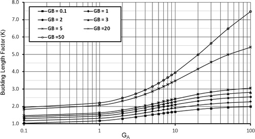
(6) )) which are solved by numerical analysis for both prevented and permitted sway frames. The results are tabulated and are plotted in two dimensional graphs that represent the relation curves between the effective length factors and the rotational restraint at one end of column at fixed value of the other rotational restraint end. Samples of these graphs are given in and . Also, these tabulated points are plotted in three dimensions to be a surface that represents the exact values of the effective length factor. Then, these curves and the surface of K-factor are compared with curves and surfaces that represent many mathematical formulas to select and adjust the best formulas which have the smallest standard error.
Fig. 2 Buckling length factor (K) for prevent of sway (Braced) columns.
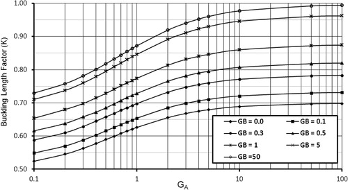
Fig. 3 Buckling length factor (K) for permitted of sway (Unbraced) columns.
Using computer software, multiple regression analyses based on the least-squared method are developed for each suggested formula to obtain the formulas which have very small standard error and less than that corresponding to the previous simple equations (French Rules). Then, very accurate and simple equations are investigated to determine the effective length factor for braced and sway steel frames as described in the following.
In case of braced frames; the equation of effective length factor is(8)
(8) where
In case of sway frames; to get good results, two equations of effective length factor are investigated according to the domain of the rotational resistance at column ends (GA, GB) as follows(9)
(9) where
and,
(10)
(10) where
Accuracy of present equations
The accuracy that we can readily measure is of course the mathematical accuracy, that is, the comparison of the results given by the obtained formulas to those obtained by solving the corresponding exact equations. First, take a look at the accuracy of the most common alignment charts and the French Rules equations.
The accuracy of the alignment charts depends essentially on the size of the chart and the reader’s sharpness of vision. This accuracy may be about five percent in small charts. On the other hand, the French Rules [Citation7] indicate that Eq. (Equation5(5)
(5) ), used for braced frames, has an accuracy of −0.50 percent to +1.50 percent while Eq. (Equation7
(7)
(7) ) used for sway frames, is accurate within two percent.
The percentage of errors for all points considered in the present regression analyses (about 300 point for each case) indicates that the investigated equations in the present work are accurate within 0.50 percent for Eq. (Equation8(8)
(8) ) of braced frames and are accurate within 1.0 percent for Eqs. (Equation9
(9)
(9) andEquation10
(10)
(10) ) of sway frames. Also, the standard error of the obtained formula Eq. (Equation8
(8)
(8) ) is about one-half of that of French Rules Eq. (Equation5
(5)
(5) ) in case of braced frames while in the case of sway frames, the standard error of Eqs. (Equation9
(9)
(9) andEquation10
(10)
(10) ) has about one-third of that of French Rules Eq. (Equation7
(7)
(7) ).
Comparison of the results
Using a few sample points, and show the comparison of the effective length factor K obtained by Eqs. (Equation8(8)
(8) –Equation(9)
(9)
(9) Equation10
(10)
(10) ) of the present work (P. W.), and that obtained by the approximate French Rules Eqs. (Equation5
(5)
(5) ,Equation7
(7)
(7) ) with those obtained by solving the corresponding exact equations for braced frames and sway frames, respectively.
Table 1 Comparison of K-factors obtained by P.W., and French Rules with exact results (side sway is prevented).
Table 2 Comparison of K-factors obtained by P.W., and French Rules with exact results (side sway is permitted).
It can be noticed that although the present equations are simple, it gave results very close to the exact values and more accurate compared with the solution by the other common simple equations (French Rules). Then, the present equations can be rather used by the design engineers with sufficient confidence.
Conclusions
In this paper, new simple closed form equations for the determination of the effective length factor K of steel columns are investigated by multiple regression analyses using the results of the exact solution. The analysis is carried out in a wide range of the rotational resistance at column ends GA, GB (from 0 to 100).
The obtained equations are simple and accurate enough for design purposes and they may be more accurate than the French rules which are recommended in some codes of steel constructions. Their simple closed forms make them easily programed within the confines of spreadsheet cell and generally well suited for computer use.
Notes
Peer review under responsibility of Housing and Building National Research Center.
References
- AISC (1986), Manual of steel construction, load and resistance factor design, American Institute of Steel Construction first ed, 1986.
- AISC (1989), Manual of steel construction, allowable stress design, American Institute of Steel Construction ninth ed, 1989.
- European Convention for Constructional steel work, European Recommendations for Steel, Construction, 1978.
- ECP (2008), Egyptian Code of Practice for steel construction (ECP), Load and Resistance Factor Design, first ed, 2008.
- ECP (2008), Egyptian Code of Practice for steel construction (ECP) Allowable Stress Design, first ed, 2008.
- M.BarakatW.F.ChenPractical analysis of semi-rigid framesAISC Eng. J.27219905468
- Pierre.DumonteilSimple equations for effective length factorAISC Eng. J.2931992111115
- Thomas C.KavanaghEffective length of framed columnsT. Am. Soc. Civ. Eng.1272196281101