
Abstract
The new Egyptian Code (ECP-201:2012) introduces new vehicular live loads (VLL) and new load combinations for the design of roadway bridges. The new VLL and load combinations introduced in ECP-201:2012 are fundamentally different than those presented in previous versions of the code. The impact of these new loads and load combinations on the design of new bridges or the structural safety of the existing bridges that have been designed according to ECP-201:2003 or ECP-201:1993 has not been fully addressed for the different bridge deck systems. Three different bridge deck systems, i.e. concrete I-shaped girders, composite steel plate girders, and concrete box-girders with different spans were numerically modeled using two-dimensional grillage analogy. The bridge decks were analyzed under main gravity loads using VLL according to ECP-201:2012 and ECP-201:2003. The internal forces of individual load cases, total un-factored load combination, and total factored load combination of ECP-201:2012 and ECP-201:2003 were compared.
The study shows that concrete box-girders designed according to ECP-201:2012 and ECP-201:2003 using the ultimate limit state method yield almost the same demand. Despite the increase in the VLL of ECP-201:2012, and consequently the live load forces, concrete I-shaped girder bridges will be subjected to less total factored internal forces in comparison to ECP-201:2003 This is attributed to the interaction between the live to dead loads ratio and the load combinations. Design of composite steel plate girder bridges according to ECP-201:2012 using the allowable stress design method yields over designed sections.
Introduction
General
The new version of the Egyptian Code of Practice (ECP) for Calculation of Loads and Forces in Structural and Masonry Works (ECP-201) that was published in 2012 (ECP-201:2012) [Citation1] introduced a new vehicular live load (VLL) for the design of roadway bridges. In addition, ECP-201:2012 presented new load combinations and new load factors to be used along with the new VLL. The VLL and load combinations used in ECP-201:2012 are fundamentally different from those used in previous versions of the code, ECP-201:2003 [Citation2]. The new VLL of ECP-201:2012 is based on the traffic loads on bridges of the Eurocode (EN 1991-2:2003) [Citation3]. ECP-201:2012 can be used for the design of conventional bridges, e.g. beam-slab bridges, box bridges, and truss bridges, with simply supported or continuous spans system and with a maximum span of 150 m. In other words, ECP-2013:2012 is applicable where small deflection theory can be justified. Bridges where large deflection theory has to be used, e.g. suspension bridges, cable-stayed bridges, are beyond the scope of the ECP-201:2012. Therefore, ECP-201:2012 is intended for the analysis and design of short- and medium-span bridges. The impact of the new VLL and load combinations of ECP-201:2012 on the design of new bridges, as well as the safety of the existing bridges that have been designed according to ECP-201:2003 has not been fully addressed for the different bridge deck systems.
Table 2 Internal forces of concrete I-shaped girder bridge with a span of 30 m.
Table 6 Internal forces of composite steel plate girder bridge with a span of 40 m.
Table 10 Internal forces of concrete box-girder bridge with a span of 40 m.
Earlier study, [Citation4] compared the earlier version of ECP-201 to other international codes for medium and long span bridges. Recent studies [Citation5,Citation6] have compared the loads of ECP-201:2012 to ECP-201:2003 as well as other international codes. It is worth noting that ECP-201:2012 was first drafted in 2008. The study was limited to concrete rectangular girders with cast-in-place slab as the bridge deck system with different spans. The study investigated the girders spacing, moment of inertia, and cross diaphragms. However, the size of the rectangular girders was kept constant despite the change in span or girders spacing. The study highlighted the impact of each parameter on live load internal forces. In addition, the study concluded that live load internal forces of ECP-201:2012 are identical to those of EN-1991-2:2003 [Citation3] and which are also more than those produced by ECP-201:2003.
Scope
This paper presents the impact of the ECP-201:2012 VLL models and load combinations on the design of different bridge deck systems with variable spans under main gravity loads. The different bridge deck systems investigated in this study are concrete I-shaped girders, composite steel plate girders, and concrete box-girders. Furthermore, the internal forces according to ECP-201:2012 and ECP-201:2003 were compared and evaluated. The design of bridge decks under laterally induced loads from wind pressures or seismic actions is outside the scope of this paper.
Vehicular live load of ECP-201
Ecp-2013:2012
ECP-201:2012 defines three different load models, namely Load Model 1 (LM1), Load Model 2 (LM2), and Load Model 3 (LM3). LM1 shall be used for the design of the different elements of the substructure and superstructure, except for bridge deck slabs. LM2 shall be used solely for the design of bridge deck slabs, whilst LM3 shall be used for pedestrian bridges only.
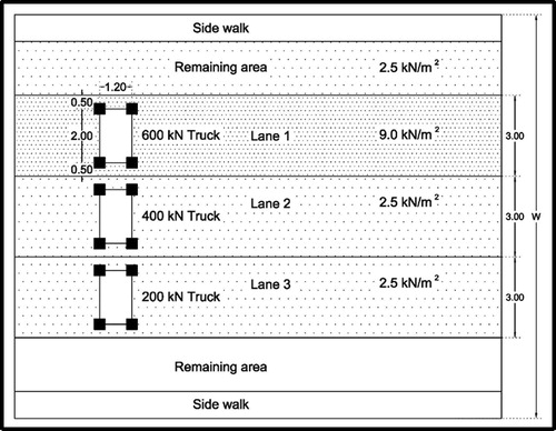
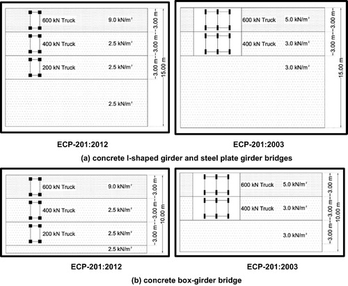
LM1 consists of a combination of concentrated loads and uniformly distributed loads. The clear roadway of the bridge is divided into a number of lanes; with a lane width of 3.0 m. the contact area of all wheels used for LM1 is 400 × 400 mm. The loads for the different lanes including the dynamic impact factor are as follows and as shown in :
| 1. | Lane 1 load comprises a two-axle, 600 kN truck with four wheels (wheel load = 150 kN). Additional to the truck load, a uniform load of 9.0 kN/m2 is to be applied to the total area of lane. | ||||
| 2. | Lane 2 load comprises a two-axle, 400 kN truck with four wheels (wheel load = 100 kN). Additional to the truck load, a uniform load of 2.5 kN/m2 is to be applied to the total area of lane. | ||||
| 3. | Lane 3 load comprises a two-axle, 200 kN truck with four wheels (wheel load = 50 kN). Additional to the truck load, a uniform load of 2.5 kN/m2 is to be applied to the total area of lane. | ||||
| 4. | The remaining width of the roadway is loaded by a unifrom load of 2.5 kN/m2. | ||||
Fig. 1 Load Model 1 of vehicular live load according to ECP-201:2012 (dimensions are in m).
ECP-201:2003 & 1993
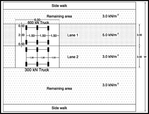
Similar to ECP-201:2012, the live load model of ECP-201:2003 & 1993 consists of combination of concentrated loads and uniformly distributed loads. The clear roadway of the bridge is divided into lanes; with a lane width of 3.0 m. The contact area of all wheels is 200 × 600 mm. The loads for the different lanes are as follows and as shown in :
| 1. | Lane 1 load comprises a two-axle, 600 kN truck with six wheels (wheel load = 100 kN). Additional to the truck load, a uniform load of 5.0 kN/m2 is to be applied to the total area of lane. | ||||
| 2. | Lane 2 load comprises a two-axle, 300 kN truck with six wheels (wheel load = 75 kN). Additional to the truck load, a uniform load of 3.0 kN/m2 is to be applied to the total area of lane. | ||||
| 3. | The remaining width of the roadway is loaded by a unifrom load of 3.0 kN/m2 | ||||
Fig. 2 Vehicular live load according to ECP-201:2003 (dimensions are in m).
It should be noted that the ECP-201:2003 live load models shall be multiplied by a dynamic impact factor, which is a function of the span under consideration.
Load Combinations of ECP-201
Since this study is concerned with main gravity loads under normal operating conditions of the bridge, only main gravity loads are included, namely, dead load (DL), superimposed dead load (SDL), and live load (LL). Torsional effects and lateral loading are outside the scope of this study.
ECP-201:2012 load combination for main gravity loads including live Load Model 1 (LM1) for characteristic load combinations is 1.35 DL + 1.35 SDL + 1.35 LL.
Neither ECP-201:2003 nor ECP-201:1993 mentioned specific load combinations to be used for bridge design. However, ECP-201:2003 refers to the load combinations given in the design code corresponding to the material utilized.
For concrete structures, ECP for Design and Construction of Concrete Structures (ECP-203:2007) [Citation7], specifies a load combination for gravity loads as 1.40 DL + 1.40 SDL + 1.60 LL. The factored load combination of ECP-203:2007 will be referenced in this paper as ECP-201:2003 for ease of comparison to ECP-201:2012.
Steel bridges are mostly designed using the allowable stress design method in accordance with the ECP for Steel Construction and Bridges (ECP 205-2001) [Citation8]. Thus, un-factored load combinations are used for steel bridge design.
ECP-201:2012 load combinations uses a live load factor much less than that used in ECP-201:2003 (1.35 versus 1.60) to mitigate the impact of using a higher VLL. This is attributed to the fact that it becomes less probable that an overloading truck will exceed the design truck of ECP-201:2012. For the dead load factor, ECP-201:2012 uses a slightly smaller factor in comparison to ECP-201:2003.
Description of comparative study
Bridge deck system
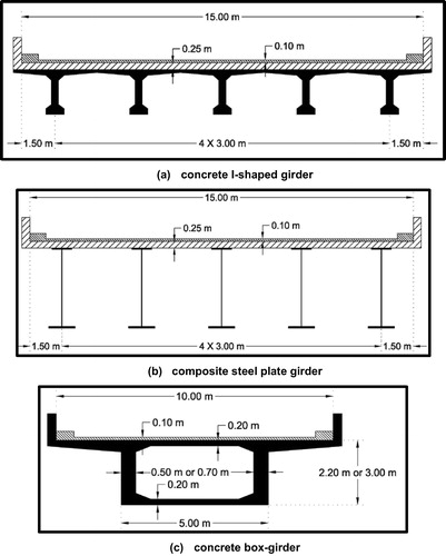
Three different bridge deck systems were analyzed, namely (i) concrete I-shaped girders, and (ii) composite steel plate girders, and (iii) concrete box-girders. shows the cross-section of the three bridge deck systems. Those three selected systems are the most widely used for short- and medium spans bridges for different reasons. Different spans for each bridge system were considered in this study. For concrete box-girder spans of 30 m, 40 m, and 60 m were considered. For concrete I-shaped girders, the spans are 20 m, and 30 m, and 40 m, while for steel plate girders, spans of 20 m, 40 m, and 60 m were considered. The most commonly used span ranges were selected for this study, so the optimum use of each system can be achieved. All bridge models considered were straight, simply supported spans only. The bridge models presented in this study closely resemble actual bridges that have been designed by the authors.
Fig. 3 Bridge deck systems presented in this study.
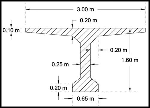
For the concrete I-shaped girders, the depth of the girders is 2.20 m for the three different spans of 20 m, 30 m, and 40 m as shown in . The same cross-section is used for 20 m span, which represents reinforced concrete girders, while for 30 m and 40 m spans they represent prestressed concrete girders with different prestressing forces. Spacing of girders was held constant for the different spans. A 250 mm cast-in-place topping slab and 100 mm wearing surface of asphalt layer were presented in the model as SDL.
Fig. 4 Cross-section of I-shaped concrete girders for spans of 20 m, 30 m, and 40 m.
For the composite steel pale girders, three different cross-sections were introduced for the three different spans. The composite sections of the steel girders including the contribution of the 250 mm cast-in-place concrete slab are shown in for the three spans. The girders spacing was kept constant for the different spans. Details of the composite sections are given in Eid (2014).
Fig. 5 Composite section of steel plate girders for different spans (dimensions in mm).
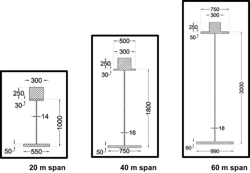
For concrete box-girders with 30 m and 40 m spans, the depth of the girder is 2.20 m and the width of the webs is 0.50 m, which is typically used for reinforced concrete box-girders as shown in . For the concrete box-girder with 60 m span, the depth of the girder is 3.00 m and the width of the webs is 0.70 m, which is mainly intended for larger spans of prestressed concrete box-girders. The top and bottom slabs of the all box-girders are 200 mm thick. A 100 mm wearing surface of asphalt layer was also included in the model.
Vehicular live load arrangement
It is common in design that edge girders experience the maximum internal forces in comparison with intermediate girders. This is mainly due to the distribution of loads from a loaded intermediate girder to the adjacent girders from both sides, while loaded edge girders can distribute to adjacent girders from one side only. Accordingly, VLL was arranged to produce the maximum internal forces in the edge girders as shown in for the three different bridge deck systems.
Fig. 6 Arrangement of live load for the different bridge models.
Numerical model
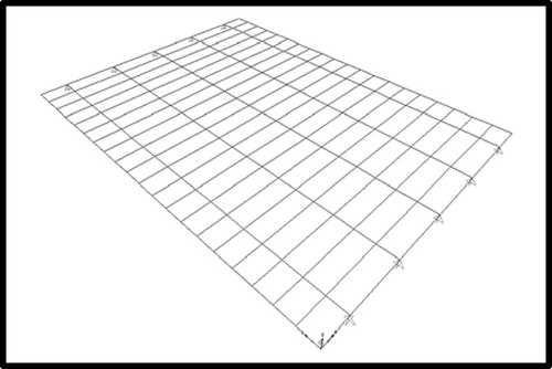
A grillage (two-dimensional) numerical model was developed for each bridge deck system and span according to Hambly [Citation9] using the commercial software “SAP 2000”. The longitudinal members of the grillage represent the composite section of the main girders, while the transverse elements represent the topping concrete slabs. The torsional constant of the longitudinal members was calculated according to the recommendation given in Hambly [Citation9]. It should be noted that the unit weight of the material defined for transverse elements was set equal to zero to avoid duplication of weight. The grillage of the steel plate girder bridge showing the arrangement of longitudinal and transverse elements is given in as a typical grillage model. More details about the numerical models can be found elsewhere [Citation10].
Fig. 7 Grillage of composite steel plate girder bridge.
Internal forces and discussion
The maximum internal forces (hereafter will be denoted as forces only for simplification) as the maximum bending moment and the maximum shear force of the edge girder under main gravity loads [dead load (DL), superimposed dead load (SDL), and live load (LL)] are reported in the following sections for each bridge system with the different spans. In addition, the total un-factored internal forces, i.e. DL + SDL + LL and the total factored internal forces (refer to section 3 for load combinations) are also presented. For comparison purposes, the ratios of the internal forces obtained according to ECP-2013:2012 to those obtained according to ECP-201:2003 are also given.
Concrete I-shaped girders
– give the internal forces of the concrete I-shaped girder bridge with spans of 20 m, 30 m, and 40 m, respectively.
Table 1 Internal forces of concrete I-shaped girder bridge with a span of 20 m.
Table 3 Internal forces of concrete I-shaped girder bridge with a span of 40 m.
It can be readily seen from the three tables that the ratio of the live load forces increases with increasing the span of the bridge. For a span of 20 m, the live load forces according to ECP-201:2012 and ECP-201:2003 were essentially the same, while for a span of 40 m, the live load forces increased by 19%. However, the increase in the live load forces did not enhance the total un-factored forces in the same amount, where the ratio of the total un-factored forces increased by 1%, 4%, and 6% for spans of 20 m, 30 m, and 40 m, respectively. This highlights the impact of the ratio of live to dead load forces. gives the ratio of the live load to total dead load for the three different spans.
Table 4 Ratio of live load to total dead load for concrete I-shaped girder bridge.
It can be readily seen from that with increasing the span of the bridge, the dead load forces become more dominant than live load forces, which mitigated the impact of the increase in the live load forces on the total un-factored forces.
Despite the increase in the live load forces due to the use of higher VLL, the total factored forces were decreased. The maximum reduction was for the 20 m span bridge with a value of 10%, while the reduction of the 30 m and 40 m spans was 5% and 2%, respectively. This signifies the effect of the live load factor of the load combinations, where the live load factor of ECP-201:2012 (1.35) is considerably less than that of ECP-201:2003 (1.60). Hence, the increase in the VLL is compensated by the lower live load factor. In addition, the slight reduction in the dead load factor helps in decreasing the total factored forces. This clearly demonstrates the invalidity of the concept of that since the VLL was increased, the design of concrete girder bridges according to ECP-201:2012 will yield higher demand in comparison to ECP-201:2003.
Composite steel plate girder bridge
– give the internal forces of the composite steel plate-girder bridge with spans of 20 m, 40 m, and 60 m, respectively.
Table 5 Internal forces of composite steel plate girder bridge with a span of 20 m.
Table 7 Internal forces of composite steel plate girder bridge with a span of 60 m.
The ratio of the live load forces increases with increasing the span of the bridge as shown in –. For a span of 20 m, the live load forces according to ECP-201:2012 and ECP-201:2003 were essentially the same, while for a span of 60 m, the live load forces increased by 25%. However, the increase in the live load forces did not enhance the total un-factored forces at the same rate, where the ratio of total un-factored forces increased by 2%, 7%, and 9% for spans of 20 m, 40 m, and 60 m, respectively. As pointed for concrete I-shaped girder bridges, the ratio of live to dead load forces shall be evaluated. gives the ratio of the live load to total dead load for the three different spans.
Table 8 Ratio of live load to total dead load for composite steel plate girder bridge.
shows that with increasing the span of the bridges, the dead load forces become more dominant than live load forces, which mitigated the impact of the increase in the live load forces on the total un-factored forces. It is worth noting that due to the higher strength of steel in comparison to concrete, the concrete I-shaped girders are stocky and bulky compared to steel I-shaped girders, especially if composite steel plate girders are used. This can be verified by comparing the ratio of live to dead load forces of the 40 m span in for concrete I-shaped girder and for composite steel plate girder.
Despite the increase in the live load forces due to the use of higher VLL, the total factored forces were decreased. The maximum reduction was in the amount of 10% for the 20 m span, while for the 60 m span, both codes ECP-201 2012 & 2003 yielded the same demand. This signifies the effect of the live load factor, where the live load factor of ECP-201:2012 of 1.35 is considerably less than that of ECP-201:2003 of 1.60. Hence, the increase in the VLL is compensated by the lower live load factor.
Based on the above discussion, design of steel bridges using the allowable stress design method will yield over designed sections. This is due to the fact that the allowable stress design method uses the total un-factored forces; hence the increase in the VLL is not compensated by the lower live load factor. Therefore, it is essential for steel bridges subjected to the VLL of ECP-201:2012 to be designed using the load and resistance factor design (LRFD) method. In case of using the LRFD design method coupled with the loads of ECP-201:2012, slightly less demand will be obtained compared to ECP-201:2003.
Concrete box-girder
– give the internal forces of the concrete box-girder bridge with spans of 30 m, 40 m, and 60 m, respectively.
Table 9 Internal forces of concrete box-girder bridge with a span of 30 m.
Table 11 Internal forces of concrete box-girder bridge with a span of 60 m.
It is confirmed that the impact of the VLL of ECP-201:2012 increases with increasing the span of the bridge. The ratio of the live load forces is 1.22, 1.27, and 1.33 for spans of 30 m, 40 m, and 60 m, respectively. The increase in the live load forces did not impact the total un-factored forces in the same amount, where the ratio of the total un-factored forces increased by 7% for all three spans of 30 m, 40 m, and 60 m, respectively. This magnifies the impact of the ratio of live to dead load forces. gives the ratio of the live load to total dead load for the three different spans.
Table 12 Ratio of live load to total dead load for concrete box-girder bridge.
Concrete box-girders are characterized by their high own weight forces compared to concrete or steel I-shaped girders. This can be verified by examining , where it can be seen that dead load forces have much higher contribution in comparison to live load forces. This resulted in a slight increase in total un-factored forces, despite the significant increase in the live load forces.
Despite the increase in the live load forces due to the use of higher VLL, the total factored forces are essentially the same for the different spans of 30 m and 40 m, and 60 m. This is attributed to the interaction between the increase in the loads and the load combinations used. This demonstrates that the design of concrete box-girders according to ECP-201:2012 or 2003 will yield the same demand.
Summary and conclusions
The new vehicular live load (VLL) and load combinations introduced by the new version of the Egyptian Code of Practice for Calculation of Loads and Forces in Structural and Masonry Works (ECP-201:2012) are fundamentally different than those presented in previous version of the code, ECP-201:2003. The impact of the new VLL and load combinations on the design of the short- and medium-span bridges has never been fully assessed.
Three different bridge deck systems, i.e. concrete I-shaped girders, composite steel plate girders, and concrete box-girders with different spans were numerically modeled using two-dimensional grillage analogy. The bridge decks were analyzed for main gravity loads using VLL according to ECP-201:2012 and ECP-201:2003. The internal forces of individual load cases, total un-factored load combination, and total factored load combination of ECP-201:2012 and ECP-201:2003 were reported and compared.
Based on the comparison of the internal forces and the findings of this study, the following conclusions can be drawn:
| 1. | The new VLL of ECP-201:2012 results in an increase in the live load internal forces. The increase in live load internal forces is more pronounced with the increase in the span of the bridge for the three bridge deck systems. | ||||
| 2. | The increase in the live load forces did not result in the same amount of increase in the total un-factored forces for all three bridge deck systems. This is attributed to the ratio of live to dead load forces. When dead load forces become more dominant, the total un-factored internal forces slightly increase. This is more significant for concrete girder bridges in comparison to steel girder bridges, due to the higher own weight of concrete girders compared to steel girders. | ||||
| 3. | Despite the increase in the VLL of ECP-201:2012, and consequently the live load forces, the total factored internal forces were decreased in comparison to ECP-201:2003 for concrete I-shaped girders. This clearly demonstrates the invalidity of the concept that due to the increase in the VLL, the design of concrete girder bridges according to ECP-201:2012 will result in a higher demand in comparison to ECP-201:2003. | ||||
| 4. | Design of steel plate girders using the allowable stress design method and VLL according to ECP-201:2013, yields over designed section. It is imperative for steel bridges subjected to the VLL of ECP-201:2012 to be designed using the load and resistance factor design (LRFD) method to account for the compensation of the increased VLL by the lower live load factor. | ||||
| 5. | Design of concrete box-girders according to the VLL of both ECP-201:2012 and ECP-201:2003 using the ultimate limit state method yields the same demand. | ||||
Conflict of interest
None.
Notes
Peer review under responsibility of Housing and Building National Research Center.
References
- ECP No. 201. Egyptian Code of Practice for Calculation of Loads and Forces in Structural and Masonry Works. Housing and Building National Research of Egypt, Giza, Egypt, 2012.
- ECP No. 201. Egyptian Code of Practice for Calculation of Loads and Forces in Structural and Masonry Works. Housing and Building National Research of Egypt, Giza, Egypt, 2003.
- EN 1991-2:2003. Eurocode 1: Actions on Structures – Part 2 Traffic Loads on Bridges, 2003.
- Bakhoum M M. Traffic Actions for the Design of Long and Medium span Roads Bridges: A Comparison of International Codes. International Association for Bridges and Structural Engineering (IABSE), Report No. 74, 1996, 541–550.
- Abduallah Medhat K. Comparison between Highway Codes for Traffic Loads on Bridge. Life Sci. J. 10(2) (2013) 621–627 (http://www.lifesciencesite.com).
- Ibrahiem Ahmed. Comparative Study of Live Loads on Bridges in Different Codes. M.Sc Thesis, Department of Civil Engineering, Faculty of Engineering at Mataria, Helwan University, Egypt, 2010.
- ECP No. 203. Egyptian Code of Practice for Design and Construction of Concrete Structures. Housing and Building National Research of Egypt, Giza, Egypt, 2007.
- ECP No. 205. Egyptian Code of Practice for Steel Construction and Bridges. Housing and Building National Research of Egypt, Giza, Egypt, 2001.
- Hambly EC. Bridge Deck Behavior. 2nd ed. E & FN SPON, Chapman & Hall, London, 1991.
- Eid Mostafa. M.Sc. Thesis, Department of Civil Engineering, Faculty of Engineering at Mataria, Helwan University, Egypt, 2014 (in preparation).