
Abstract
This paper focuses on experimental and analytical behavior of the ultimate moment of the connections of steel I-beams to square concrete-filled steel tube columns. External stiffeners around the columns are used at the beam flange levels. Five specimens are tested monotonically. The test parameters are the column stiffener dimensions and filling the steel tube column with concrete. Two types of failure modes are observed; beam flange failure and stiffener failure. The experimental results show that the ultimate moment of the connection is increased by increasing stiffener’s dimensions and filling the steel tube column with concrete. ANSYS finite element program is used to simulate the behavior, taking into account both geometric and material nonlinearities. Analytical results that are in fair agreement with the experimental ones are then used to discuss the influence of the main geometric parameters on the connection behavior. The parameters are the stiffener and column dimensions as well as filling the steel tube column with concrete. Different square column cross sections are chosen to cover the three classes of section classifications according to Egyptian code of practice, which are: compact, non compact or slender. The increase in the ultimate moment of the connections is based upon both column cross sections’ compactness and stiffener dimensions while the maximum advantages occur with slender columns.
Introduction
Concrete-filled steel tube (CFT) columns combine the ductility generally associated with steel structures with the stiffness of concrete components. They have many advantages compared to other composite column types such as: the steel tube provides a convenient formwork for the concrete; it prevents spalling of concrete and the concrete core delays local buckling of the steel tube. Also, the steel tube provides continuous confinement for the concrete-filling which helps the column to offer favorable ductility. Consequently, CFT columns may be well suited for buildings constructed in regions at high seismic risks. However, their use has been limited due, in part, to the difficulties in the design and detailing of satisfactory connections, and to the lack of construction experience of such columns.
Fig. 3 Schematic drawing of specimen CS-50-12.
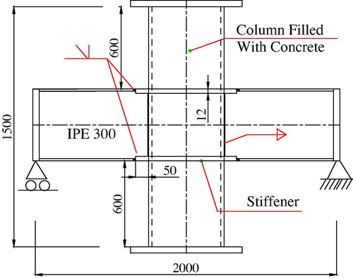
Fig. 4 Schematic drawing of specimen CS-75-12.
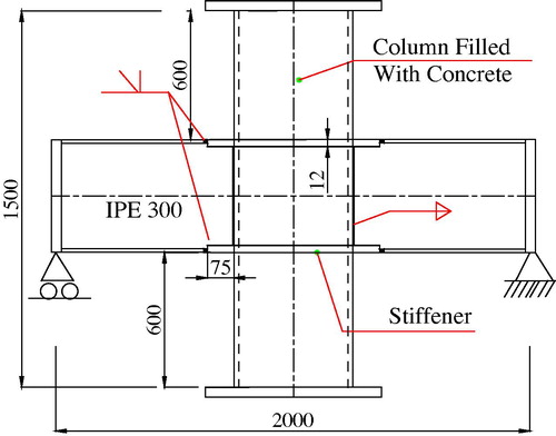
Fig. 5 Schematic drawing of specimen CS-50-6.
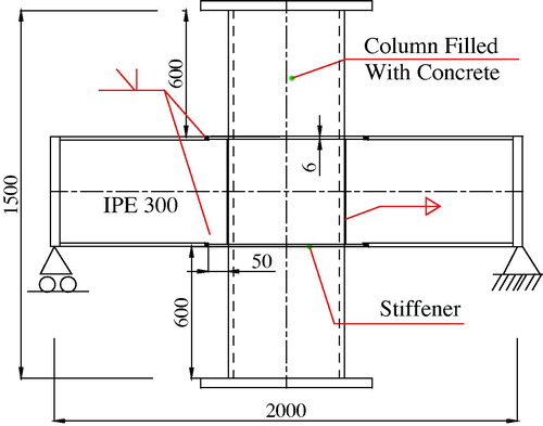
Fig. 12 Vertical displacement of beam flange measured by LVDT 2 versus applied load for specimen CS-50-6.
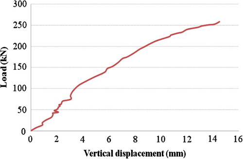
Fig. 21 Mult/Mp ratio versus tst for column S-b with different bst.

Fig. 22 Mult/Mp ratio versus tst for column S-c with different bst.
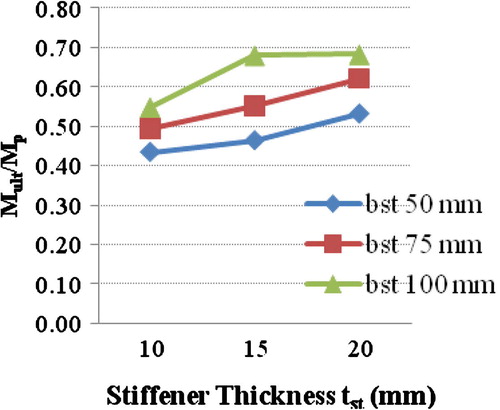
Fig. 23 Mult/Mp ratio versus tst for column S-d with different bst.
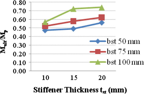
Fig. 24 Mult/Mp ratio versus tst for column S-e with different bst.
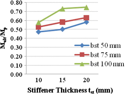
Fig. 27 Mult/Mp ratio versus tst for square columns not filled (S-b-2) and filled with concrete (S-b-20).
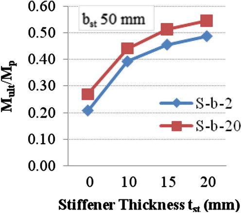
Fig. 28 Mult/Mp ratio versus tst for square columns not filled (S-c-3) and filled with concrete (S-c-21).
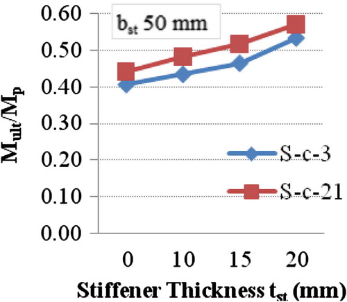
Fig. 29 Mult/Mp ratio versus tst for square columns not filled (S-d-4) and filled with concrete (S-d-22).
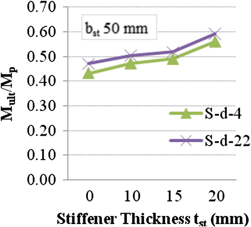
Fig. 30 Mult/Mp ratio versus tst for square columns not filled (S-e-5) and filled with concrete (S-e-23).
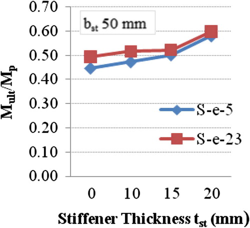
Fig. 31 Mult/Mp ratio versus tst for square columns not filled (S-f-6) and filled with concrete (S-f-24).
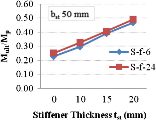
Fig. 32 Mult/Mp ratio versus tst for square columns not filled (S-a-7) and filled with concrete (S-a-25).
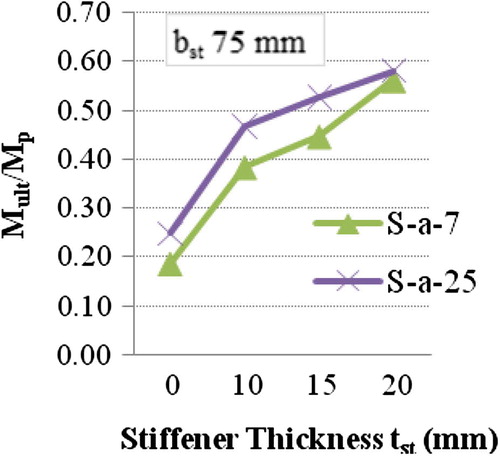
Fig. 33 Mult/Mp ratio versus tst for square columns not filled (S-b-8) and filled with concrete (S-b-26).
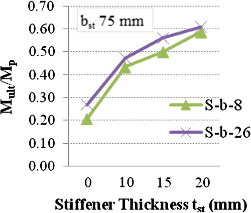
Fig. 34 Mult/Mp ratio versus tst for square columns not filled (S-c-9) and filled with concrete (S-c-27).
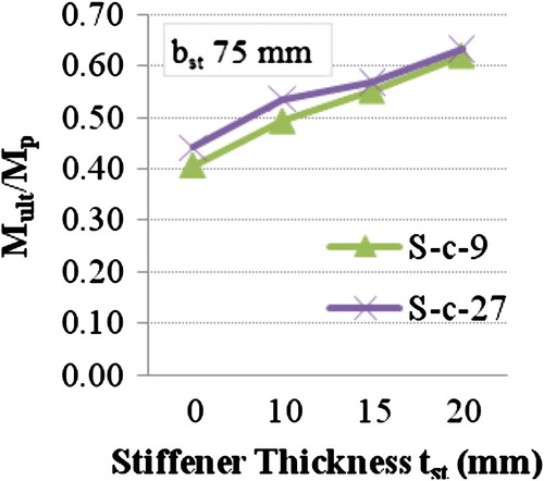
Fig. 35 Mult/Mp ratio versus tst for square columns not filled (S-d-10) and filled with concrete (S-d-28).
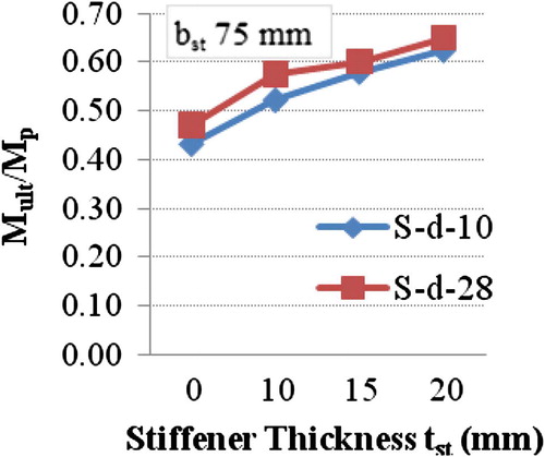
Fig. 36 Mult/Mp ratio versus tst for square columns not filled (S-e-11) and filled with concrete (S-e-29).
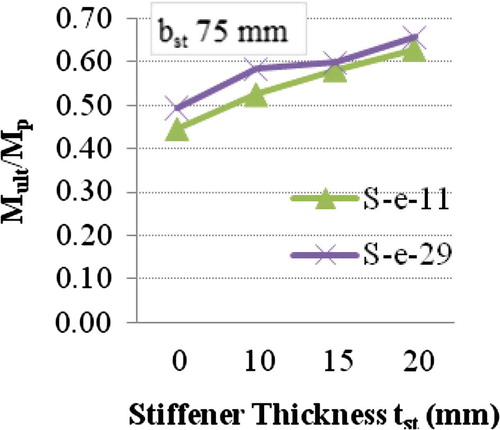
Fig. 37 Mult/Mp ratio versus tst for square columns not filled (S-f-12) and filled with concrete (S-f-30).
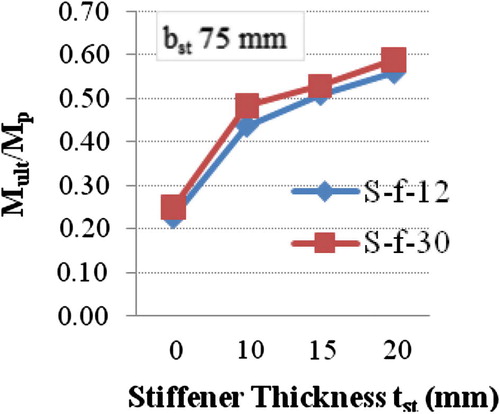
Fig. 38 Mult/Mp ratio versus tst for square columns not filled (S-a-13) and filled with concrete (S-a-31).
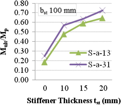
Fig. 39 Mult/Mp ratio versus tst for square columns not filled (S-b-14) and filled with concrete (S-b-32).
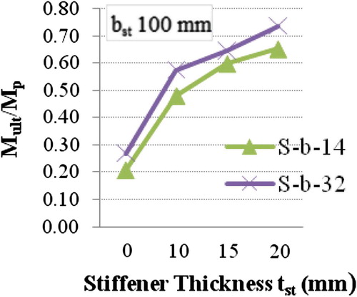
Fig. 40 Mult/Mp ratio versus tst for square columns not filled (S-c-15) and filled with concrete (S-c-33).

Fig. 41 Mult/Mp ratio versus tst for square columns not filled (S-d-16) and filled with concrete (S-d-34).
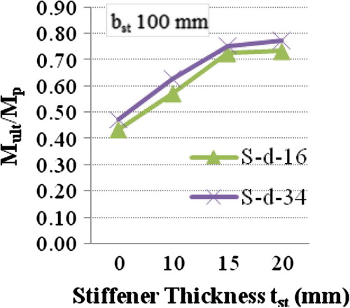
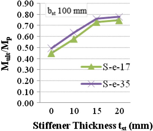
Fig. 42 Mult/Mp ratio versus tst for square columns not filled (S-e-17) and filled with concrete (S-e-35).
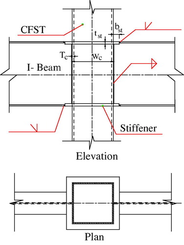
Several researches have been carried out for decades on different types of moment connections of steel I-beams to square tube columns. The most widely used connection type is the external stiffeners that surround the tube columns, as shown in . The use of external stiffeners increases the ultimate moment of the connection most significantly. The force transfer mechanism of such connection is discussed and verified against experimental program [Citation1]. The static strength of steel I-beam to rectangular hollow column section connections is a thesis that consists of experimental and numerical investigations [Citation2]. The influence of concrete filling of the columns as well as the effect of a composite floor on the behavior and strength of such connection are included. Ultimate moment of such connections is improved by the presence of stiffeners around the column or by filling the column with concrete because the deterioration of the connection due to failure in column wall is prevented by shifting the stress concentration away from the column wall. Other research works [Citation3-Citation[4]Citation[5]Citation[6]Citation[7]Citation[8]Citation9] have been carried out to study the behavior of moment connections of steel I-beams to steel tube columns.
Fig. 1 Steel I-beam welded to square tube column.
In this paper, five experimental tests were carried out monotonically. The test parameters are the column stiffener dimensions and filling the steel tube column with concrete. A finite element analysis is presented to model the non-linear behavior of the in-plane moment connections between steel I-beams and square steel tube columns with stiffening plates around the columns under vertical loads only, no lateral loads are considered. The analytical results are verified against the experimental. The finite element model is used to conduct a parametric study with different dimensions of square columns, stiffeners and filling the column with concrete.
Test arrangement and procedure
General
An experimental program of five specimens has been conducted to investigate the behavior of moment connections between steel I-beams and CFT columns. Some parameters are taken constant throughout the tests such as: the square column cross section dimensions are 250 × 10, the cross section of the beam is IPE 300, the length of the column is 1500 mm, and the total beam span between end supports is 2000 mm. – illustrate schematic drawings of each specimen showing the location of stiffener and other dimensions. Each steel tube column is fillet welded to a lower end plate of 50 mm thickness at the bottom, while the top end is kept open to allow filling the tube with concrete. Stiffening plates are welded to the tube column using fillet welds. Beam flanges are welded to stiffening plates using complete penetration groove welds, and the beam web is welded to the tube column using fillet welds. For convenience, each specimen has an individual designation involving two letters followed by a series of numbers, as tabulated in . The first letter represents the presence of concrete inside the column, “N” for column not filled with concrete, “C” for column filled with concrete. The second letter represents shape of stiffener, “S” for square shaped column stiffener, “I” for inclined side column stiffener. Meanwhile, the numbers following the letters denote stiffener width (bst) followed by stiffener thickness (tst) in mm.
Fig. 2 Schematic drawing of specimen NS-50-12.
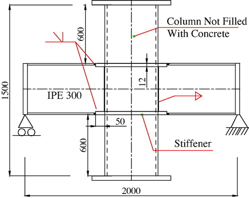
Fig. 6 Schematic drawing of specimen NI-50-12.
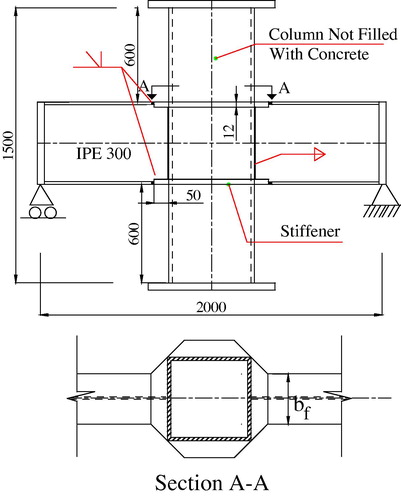
Table 1 Specimens and stiffener dimensions for current experimental program.
Material properties of test specimens
Specimens CS-50-12, CS-75-12 and CS-50-6 are filled with concrete of compressive strength 35 MPa, which is the average compressive strength of five concrete cubes that are cast and tested on the same day as the specimens, and had a minimum age of 28 days prior to testing. An expanding grout admixture providing volume expansion and increasing fluidity without segregation is used. Four steel tensile coupons are cut from each flat steel sheet before manufacturing and tested under tension. The results of the tests show that the steel yield strength, Fy, is 390 MPa for columns, Fy, is 410 MPa for all stiffeners except for thickness 6 mm, where Fy, is 261 MPa. Finally, for the beams Fy, is 250 MPa, and the modulus of elasticity of steel, Es, is 200,000 MPa.
Test setup and loading
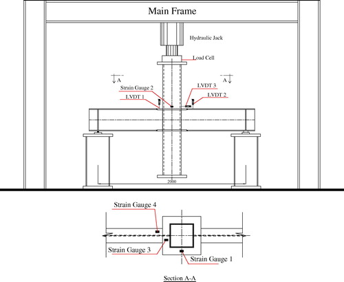
The specimens are centered in the testing machine to ensure that the compressive axial load is applied without any eccentricity. The top end of the steel tubes is covered first with the cap plate of thickness 50 mm and then rested on the upper bearing of the testing machine which itself rests on a ball bearing to allow rotation in all directions. Column load, as measured by test machine load cell, is applied at very slow rate and is maintained for about one minute to record the measurements. So, the connection between steel I-beams and square tube columns will be subjected to in-plane moment and the column is not preloaded. To produce two pin ends of the beams, the beam end is rested on a roller bearing. This roller bearing consists of two thick plates 200 × 200 mm with 40 mm thickness, and the two plates have a groove of depth 8 mm. A cylindrical roller of diameter 40 mm is placed above the two plates to allow end rotation without sliding. shows a schematic drawing for the loading and instrumentation setup.
Fig. 7 Test setup for the specimens and arrangement of LVDTs and strain gauges.
Instrumentation
The load cell, which is used to record the applied load, is placed between the top end of the specimen and the testing machine. The values of ultimate moment of the connections are obtained as the reaction force at the beam support, which is half the value measured by load cell, multiplied by the distance between the beam support and the beam-to-column connection. LVDTs monitor the vertical movement of the stiffener plate at the beam position (LVDT 1), the vertical movement of the beam compression flange (LVDT 2), and the horizontal movement of the column wall at the beam compression flange position (LVDT 3). Strain gauges 1 and 2 are located, on the sides that are not connected to beam flange, at the stiffener plate and at column steel wall, respectively. Also, the strain gauges are placed at stiffener plate welded to the beam flange width (strain gauge 3) and finally, at the edges of beam compression flange (strain gauge 4). shows also the arrangement of LVDTs and the strain gauges. All the measurements are recorded directly in the computer by a data acquisition system and curves are plotted automatically.
Experimental results and discussions
The pertinent measurements are expressed in terms of the applied experimental load versus the vertical deformation of stiffener plate, beam flange, column steel wall inward deformation, and longitudinal strains which are measured using strain gauges. The ultimate moment of the connection of each specimen, MEXP., is given in . Also, this table shows the ultimate moment obtained by the proposed numerical analysis that will be explained later in Section 4. It can be noticed that, the ultimate moment increases by 45%, when the column is filled with concrete. When bst is increased from 50 mm to 75 mm, the ultimate moment increases by 10%, but when tst is increased from 6 mm to 12 mm, the increase is 57%. For more details of the test results, refer to Fawzy [Citation10]. Future cyclic testing of such connections is recommended to reach a full conclusion on their structural adequacy.
Table 2 Comparison between ultimate moment obtained by current experiments and those obtained by the proposed finite element model.
Failure modes
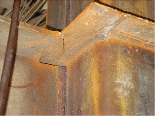
shows the deformed shape during test for specimen NI-50-12. The presence of stiffeners causes failure of all specimens at the beam compression flange due to local buckling, except for specimen CS-50-6, in which failure occurs at the stiffener, as shown in .
Fig. 8 Deformed shape during test for specimen NI-50-12.
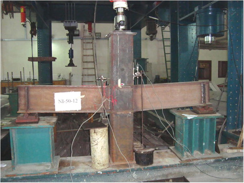
Fig. 9 Stiffener failure for specimen CS-50-6.
Displacements
shows the test loads and the corresponding maximum displacement values recorded by the different LVDTs. In all tests, LVDTs from 1 to 3 show that the relationship is nonlinear, characterized by an ascending branch up to failure and the maximum displacement at failure is considerably increased. For specimen CS-50-12, where column is filled with concrete, local buckling of the stiffener and of the beam compression flanges is decreased by 90% and 25%, respectively, compared to specimen NS-50-12. By decreasing the thickness of the stiffener to 6 mm, its vertical displacement increases by 53% and the local buckling of the beam compression flange decreases by 20%. In specimen NI-50-12, the stiffener shape has no sharp edges, thus the local buckling decreases by 14% and 30% for stiffener and beam compression flange, respectively, with respect to specimen NS-50-12. The face of the column steel wall of specimens NS-50-12 and NI-50-12 deforms inward at the compression flange location by 3 mm and 6 mm, respectively. The deformations decrease when the specimens are filled with concrete, causing displacement of 2 mm for specimen CS-50-12 and 1.5 mm for specimen CS-75-12. So, the ductility of the connection increases by not filling the tube with concrete and by reducing stiffener thickness, but the ultimate moment is reduced. shows horizontal displacement of column steel wall measured by LVDT 3 for specimen NS-50-12. It can be noticed that the displacement decreases under load in the lower part before it increases, since column wall may not yet started obtaining the load from the beam. Also, – show vertical displacement of beam flange measured by LVDT 2 for specimens NI-50-12, CS-50-6 and CS-50-12, respectively.
Fig. 10 Horizontal displacement of column steel wall measured by LVDT 3 versus applied load for specimen NS-50-12.
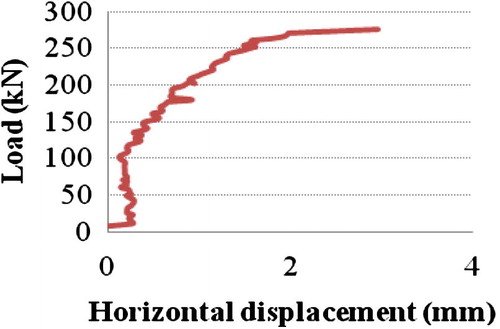
Fig. 11 Vertical displacement of beam flange measured by LVDT 2 versus applied load for specimen NI-50-12.
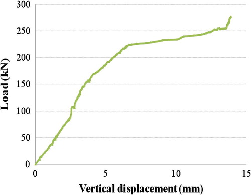
Fig. 13 Vertical displacement of beam flange measured by LVDT 2 versus applied load for specimen CS-50-12.
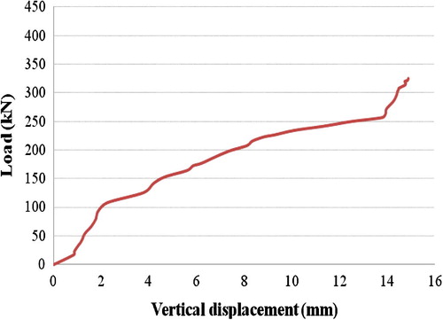
Table 3 Test loads and the corresponding maximum values recorded by LVDTs (mm).
Strains
shows the test loads and the corresponding maximum strain values recorded by the different strain gauges. The common feature in strain curves is that the relationship is directly proportional to failure. Filling the column with concrete decreases the strains recorded by strain gauges 1 and 2 by 95% and 88%, respectively, as the concrete decreases the local buckling of the adjacent elements. However, Strain gauge 3 shows an increase in the strains by three times, which signifies the role of concrete that shifts the local buckling waves toward the stiffener zone and accordingly, strain gauge 4 detects a decrease in the strains by 48%.
Table 4 Test loads and the corresponding maximum strain values recorded by strain gauges (micro strain).
Local buckling of the stiffener is inevitable as bst increases and tst decreases. The increase in the strains measured by strain gauge 1 is almost 3.6 times for specimen CS-75-12 compared to CS-50-12 and is 4.5 times for specimen CS-50-6 compared to CS-50-12. Similarly, the strains, recorded by strain gauge 2, increase by 38% for specimen CS-75-12 compared to CS-50-12, but almost are not affected by changing tst. Also, by increasing bst, the strains decrease by 66% as a result of redistribution at the location of strain gauge 3. The strains recorded by strain gauge 4 at beam compression flange are doubled in specimen CS-75-12 compared to CS-50-12, meanwhile, it increases by 11% in specimen CS-50-6 compared to specimen CS-50-12. and show average micro strain for specimen CS-50-6 of stiffener by strain gauge 1 and of beam flange by strain gauge 4, respectively.
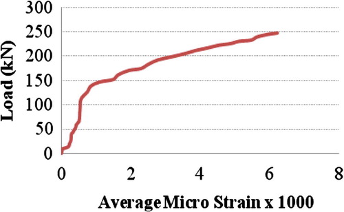
Fig. 14 Average micro strain of stiffener by strain gauge 1 versus applied load for specimen CS-50-6.
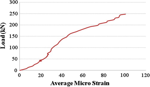
Fig. 15 Average micro strain of beam flange by strain gauge 4 versus applied load of specimen CS-50-6.
The least value of the strains is recorded by strain gauge 1 that is located at specimen NI-50-12, compared to NS-50-12, as a sign of the small portion of the stresses passing around the column wall. Also, a decrease in the strains by 35%, at the location of strain gauge 2 is noticed. However, there is an increase in the strains recorded by strain gauge 3 by 5%, accompanied by a decrease of 24% in the strains that are recorded by strain gauge 4. Although the shape of the stiffener influences the stress path through the connection, the ultimate moment of the connection is slightly affected between specimens NS-50-12 and NI-50-12.
Numerical analysis
In order to provide a wide parametric study of the behavior of moment connections between steel I-beams and square CFT columns, a three dimensional finite element model has been developed. Both material and geometric nonlinearities are taken into consideration. The steel tube, concrete core, steel beams, column stiffener and the end plates are defined in the ANSYS program [Citation11] as individual bodies. Element type for steel parts is Shell 43 which has membrane and bending capabilities and has six degrees of freedom at each node; three translations and three rotations. The weld is idealized by providing common nodes for the steel beam, stiffeners and column tube at the weld locations. SOLID 65 is used to model the concrete. The solid element has eight nodes with three transitional degrees of freedom at each node. In addition, the element is capable of simulating plastic deformation, cracking, crushing and also, simulating creep of concrete in three orthogonal directions. To simulate the bond between the steel tube and the concrete core, contact element CONTA 174 is used [Citation12]. It allows the contact pressure to be transmitted between the concrete and the steel tube when they are in contact, while no pressure is transmitted if separation occurs, so no tension is allowed to be transmitted between the two surfaces. The friction between the two faces is maintained as long as they remain in contact. Material properties of the column steel wall, stiffener plates and steel beam are defined by the tensile test results of coupons taken from specimens. Yield stress, shear modulus, and Poisson’s ratio of the end column plates are as those of the steel shell element but with higher modulus of elasticity to avoid the deformations of the plates. A uniaxial stress strain relationship is used to model concrete in compression taking confinement into consideration [Citation13].
To simulate the boundary conditions, the end surfaces of the column are assumed free to move while the ends of steel beams are restrained. One end of the steel beam is hinge while the other is roller. To simulate the column under axially concentric load, a distributed pressure is applied at the surface of the upper end plate incrementally until failure takes place. Solution technique is the arc length method. This method is used as an incremental control technique between nodal force and nodal displacements. Modified Newton Raphson method is used as an iterative solution.
Comparison between experimental and analytical results
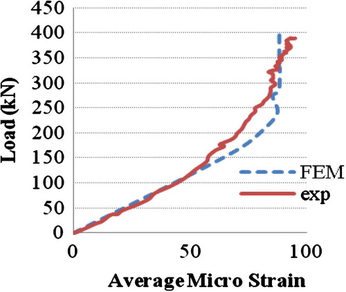
shows also the ultimate moment of the connection of finite element analysis, MFEM. Fair agreement is achieved between both experimental and analytical results for most specimens. As expected, the analytical model shows results higher than the experimental for most specimens, due to the perfect conditions assumed for the finite element model, for example, the effect of weld and residual stresses are not included. shows the average micro strain obtained from strain gauge 3 versus applied load relationship for specimen CS-50-6 for both finite element model and experimental results. Similarly, illustrates the strain measured from strain gauge 2 for specimen CS-50-12. It can be noticed that the two curves are almost identical with good agreement. Another verification of the analytical model is carried out against the experimental work presented by Park et al. [Citation1] and is published in Dessouki et al. [Citation14].
Fig. 16 Average micro strain by strain gauge 3 versus applied load calibrating finite element model with experimental test for specimen CS-50-6.
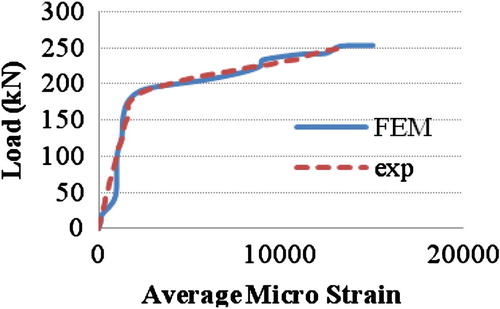
Fig. 17 Average micro strain by strain gauge 2 versus applied load calibrating finite element model with experimental test for specimen CS-50-12.
Parametric study
A parametric study is conducted using the proposed finite element model. The first parameter is the presence of a square shaped stiffener around the column at the beam flange levels. The studied bst are 50, 75 and 100 mm and tst are 10, 15 and 20 mm. The models that are not filled with concrete are compared with others that are filled with concrete of compressive strength 35 MPa, which is the second parameter. The third parameter is the columns’ cross section dimensions that are given in . Six different column cross sections are chosen to cover the three classes of section classifications according to ECP [Citation15], which are: compact, non compact or slender. For convenience, each specimen has an individual designation involving two letters followed by a number. The first letter represents the square column shape “S”, and the second letter represents column cross section defined by (Wc × Tc). Meanwhile, the number following the two letters, shown in , denotes the sample number.
Table 5 Square column cross sections used in the analytical study.
Table 6 Ultimate moment of the connections between beam IPE 400 and square columns not filled with concrete and using different stiffener dimensions.
Some values are constant throughout this study for instance, the length of the investigated tubular columns is 3000 mm, the length of the investigated beam that is connected to the mid-height of the column, is 1000 mm on each side of the column wall and finally, the beam cross section is IPE 400. The curves are plotted showing a non dimensional ratio between ultimate moment of the connection to the plastic moment of the beam (Mult/Mp) versus bst or tst.
Results and discussions of numerical analysis
shows the effect of changing stiffener and square column cross section dimensions on the ultimate moment of the connections; while demonstrates the effect of filling the column with concrete only or using both stiffeners and filling the column with concrete.
Table 7 Ultimate strength of moment connections between beam IPE 400 and square columns filled with concrete and using different stiffener dimensions.
Failure modes
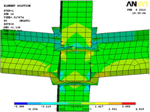
Three different failure modes are observed from the stress distributions plotted on the deformed shapes. First, failure occurs at the column steel walls that are un-stiffened for both not filled and filled with concrete columns, due to high distortion of the un-stiffened tube, which is obvious in . Second, failure is at the stiffener for connections with stiffener widths 50 and 75 mm as well as with stiffeners 100 × 15 or 100 × 10, which occurs by the stress path around the steel tubes that are not filled or filled with concrete, as shown in . Third, failure occurs at beam compression flange for connections with stiffener 100 × 20 and columns not filled or filled with concrete. The concrete filling almost has no effect on changing the location of the failure modes; however, it reduces significantly the deformations of the column wall and the stiffeners. Generally, failure modes on both column walls and on stiffeners should be avoided to move the plastic hinging zone away from the column and obtain ductile connections.
Fig. 18 Stress distribution (t/cm2) of un-stiffened square column 300 × 10 not filled with concrete.
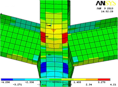
Fig. 19 Stress distribution (t/cm2) of square column 300 × 10 with stiffener 50 × 20 not filled with concrete.
The inward deformations of the column steel wall at the beam compression flange zone is up to 5.7 and 1.5 mm for columns that are not filled and filled with concrete, respectively, which is attributed to the column cross section dimensions. Presence of the stiffener reduces these deformations to 2.7 and 1.6 mm for stiffener widths 50 and 100 mm, respectively. When the columns are stiffened and filled with concrete, these deformations reduce to 1.6 mm and 1.1 mm. The total rotation of the connection is calculated as the beam tip displacement divided by half of the beam depth. The un-stiffened columns show rotation ±0.028 rad and ±0.0075 rad for columns not filled and filled with concrete, respectively. When the columns are stiffened and not filled with concrete, the rotations are ±0.014 rad and ±0.008 rad for stiffener widths 50 and 100 mm, respectively. The rotation of the connection is reduced when the column is filled with concrete by 73% for un-stiffened columns, 40% and 31% for columns with stiffener widths 50 and 100 mm, respectively.
Effect of stiffener dimensions
The presence of stiffeners around the column increases the ultimate moment of the connection. This increase (which is up to 3.47 times for columns S-a compared to the un-stiffened connections) is directly proportional to the stiffener dimensions, as shown in –. With respect to different column cross sections, and using maximum stiffener dimensions 100 × 20, the ultimate moment of the connections increases by about 3.14 times for columns S-b and S-f, and by about 1.68 times for columns S-c, S-d, and S-e compared to the un-stiffened connection. The influence of each stiffener dimension is studied separately. For example, with compact columns S-a, by increasing the stiffener width from 50 to 75 mm, the ultimate moment of the connection increases by up to 19% and this increase is up to 37% with stiffener width 100 mm. Meanwhile, for non-compact columns S-c, this increase is up to 19% and 47% when increasing stiffener width from 50 to 75 mm and from 50 to 100 mm, respectively. Finally, for slender columns S-f, the increase is up to 31% and 64%. Moreover, changing stiffener thickness from 10 to 15 mm increases the ultimate moment of the connection by up to 27% while this increase is up to 58% by changing stiffener thickness from 10 to 20 mm. It can be noticed that the results are based upon both column cross section compactness and stiffener dimensions and the maximum advantages occur with slender columns and with stiffener width 100 mm. Also, the figures show that all the ultimate moment ratios (Mult/Mp) are less than one which indicates that the beam is stronger than the stiffener. This is one of the research objectives to cause failure in the connection and demonstrate the effect of stiffener dimensions. Extension to the obtained results is proposed in the future work by increasing stiffener thickness till reaching the plastic moment of the beam.
Fig. 20 Mult/Mp ratio versus tst for column S-a with different bst.
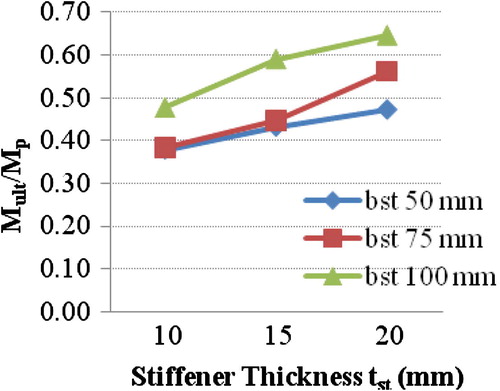
Fig. 25 Mult/Mp ratio versus tst for column S-f with different bst.
Effect of filling the column with concrete
Although the effect of filling the column with concrete is not a new parameter to be investigated, it is adopted only to demonstrate the comparison between both cases and show the value of concrete filling in increasing the ultimate moment of the connection and decreasing the column local buckling. Presence of concrete inside un-stiffened square columns increases the ultimate moment of the connections by about 33% for columns S-a and S-b, as well as by about 10% for columns S-c, S-d, S-e and S-f compared to those not filled with concrete. The results in show that the ultimate moment of the connections depends upon the cross section of column, where the local buckling is delayed by the presence of concrete.
Effects of using both stiffeners and filling the column with concrete
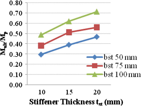
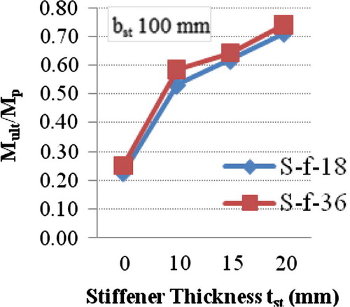
This section combines the effect of using both stiffeners and filling the column with concrete, as shown in –. The maximum increase in the ultimate moment of the connections occurs for columns S-a filled with concrete and stiffened with stiffener width 100 mm which is about 3.89 times compared to un-stiffened columns not filled with concrete, as noted in . However, with respect to other column cross sections, this increase is 3.55 times for columns S-b, 3.25 times for columns S-f, and is about 1.8 times for columns S-c, S-d, and S-e. Also, with respect to stiffener dimensions, by increasing stiffener width from 50 to 75 mm, the ultimate moment of the connections increases by up to only 16% and this increase is up to 45% with stiffener width 100 mm for both compact columns S-d and non-compact columns S-e. Meanwhile, this increase is up to 30% and 65% for slender columns S-f. Moreover, changing stiffener thickness from 10 to 15 mm increases the ultimate moment of the connection by up to 26% while this increase is up to 50% by changing stiffener thickness from 10 to 20 mm. So, the most effective results in increasing the ultimate moment of the connections with respect to changing stiffener dimensions and filling the column with concrete occur with slender columns S-f.
Fig. 26 Mult/Mp ratio versus tst for square columns not filled (S-a-1) and filled with concrete (S-a-19).
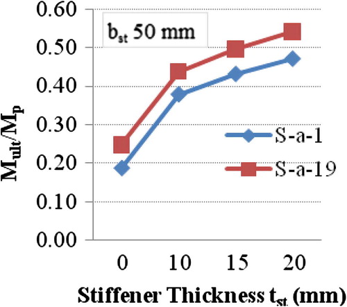
Fig. 43 Mult/Mp ratio versus tst for square columns not filled (S-f-18) and filled with concrete (S-f-36).
Conclusions
Five experimental tests were carried out and loaded monotonically. The test parameters are column stiffener dimensions and filling the steel tube column with concrete. Analytical study was performed using ANSYS program to predict the ultimate moment of connections between steel I-beams and square tube columns with stiffening plates around the columns. A parametric study was conducted on different column cross sections and stiffener dimensions as well as filling the tube column with concrete. The following conclusions are drawn based on the experimental and analytical studies:
| 1. | Three failure modes are observed in the connections; steel column wall failure for un-stiffened columns, as well as stiffener or beam compression flange failure for stiffened columns. The ductility of the connection is bigger for tubes not filling with concrete and for the cases of reduced stiffener thicknesses, but the ultimate moment is reduced. | ||||
| 2. | The shape of the stiffener affects the stress distribution through the connection but does not almost affect the ultimate moment of the connections. Also, sharp corners are not recommended for the stiffeners due to the stress and strain concentrations at these points. | ||||
| 3. | The horizontal displacement of the column steel walls is decreased considerably by filling the column with concrete as the local buckling is shifted toward the stiffener zone and accordingly, the strains at the beam flanges decrease. | ||||
| 4. | Increasing stiffener dimensions improves the ultimate moment of the connection by up to 65% and redistributes the stresses in the stiffener. | ||||
| 5. | Presence of stiffeners around the column perimeter increases the ultimate moment of the connection by up to 3.5 and 3.9 times compared to un-stiffened columns for columns that are not filled and filled with concrete, respectively. | ||||
| 6. | Filling the columns with concrete may increase the ultimate moment of the connection by up to 33% and 22% for un-stiffened and stiffened columns respectively compared to columns not filled with concrete, depending upon the column cross section dimensions. | ||||
| 7. | Filling the columns with concrete decreases the rotation of the connection by 73% for un-stiffened columns, 40% and 31% for columns stiffened with stiffener widths 50 and 100 mm, respectively. | ||||
| 8. | The increase in the ultimate moment of the connections is based upon both column cross sections’ compactness and stiffener dimensions and the maximum advantages occur with slender columns. | ||||
Conflict of interest
None.
Acknowledgements
The experimental work presented in this research was carried out at the Structural Engineering Laboratory, Faculty of Engineering, Tanta University, Egypt. Specifically, the authors would like to thank and appreciate the help provided by Prof. Dr. Mohamed Ahmed Dabaon, Professor of Steel Structures and Bridges and Vice President of Tanta University.
Notes
Peer review under responsibility of Housing and Building National Research Center.
References
- J.W.ParkS.M.KangS.C.YangExperimental studies of wide flange beam to square concrete-filled tube column joints with stiffening plates around the columnJ. Struct. Eng. ASCE122005131140
- L.H. Lu, The static strength of I-beam to rectangular hollow section column connections (Ph.D. thesis), Faculty of Civil Engineering and Geosciences, Delft University of Technology, 1997.
- S.R.MirghaderiS.TorabianF.KeshavarziI-beam to box–column connection by a vertical plate passing through the columnEng. Struct.328201020342048
- C.PetrusH.Abdul HamidA.IbrahimG.ParkeExperimental behaviour of concrete filled thin walled steel tubes with tab stiffenersJ. Constr. Steel Res.6672010915922
- J.WangL.HanB.UyBehaviour of flush end plate joints to concrete-filled steel tubular columnsJ. Constr. Steel Res.652009925939
- Q.Q.LiangPerformance-based analysis of concrete-filled steel tubular beam–columns. Part I: Theory and algorithmsJ. Constr. Steel Res.6522009363372
- Y.KimK.ShinW.KimEffect of stiffener details on behavior of CFT column-to-beam connectionsSteel Struct.82008119133
- K.ShinY.KimY.OhT.MoonBehavior of welded CFT column to H-beam connections with external stiffenersEng. Struct.26200418771887
- T.FukumotoSteel beam to concrete-filled steel tube column, moment connections in JapanSteel Struct.52005357365
- M.M. Fawzy, Moment connections of beams and concrete-filled steel columns (Ph.D. thesis), Faculty of Engineering, Ain Shams University, 2013.
- ANSYS, finite element program, Swanson Analysis System Inc., Release 12.1, 2009.
- Y.K.JuY.KimS.KimFEM Analysis on Structural Behavior of CFT Column to Flat Plate Slab Connection2004University of TexasAustin
- J.M.GereS.P.TimoshenkoMechanics of Materials1997PWS Publishing CompanyBoston, MA
- A.K.DessoukiA.H.YousefM.M.FawzyMoment connections of steel I-beams and square concrete-filled steel tube columnsCivil Eng. Res. Mag. Al-Azhar Univ.3522013668684
- ECP No. (205), Egyptian code of practice for steel construction and bridges, allowable stress design (ASD), 2001.