
 ?Mathematical formulae have been encoded as MathML and are displayed in this HTML version using MathJax in order to improve their display. Uncheck the box to turn MathJax off. This feature requires Javascript. Click on a formula to zoom.
Abstract
Prestressed concrete is widely used in the construction industry in buildings. And corrosion of reinforcing steel is one of the most important and prevalent mechanisms of deterioration for concrete structures. Consequently the capacity of post-tension elements decreased after exposure to corrosion. This study presents results of the experimental investigation of the performance and the behavior of partially prestressed beams, with 40 and 80 MPa compressive strength exposed to corrosion. The experimental program of this study consisted of six partially prestressed beams with overall dimensions equal to 150 × 400 × 4500 mm. The variables were considered in terms of concrete compressive strength, and corrosion location effect. The mode of failure, and strain of steel reinforcement, cracking, yield, ultimate load and the corresponding deflection of each beam, and crack width and distribution were recorded. The results showed that the partially prestressed beam with 80 MPa compressive strength has higher resistance to corrosion exposure than that of partially prestressed concrete beam with 40 MPa compressive strength. Not big difference in deterioration against fully/partially corrosion exposure found between partially prestressed beams at the same compressive strength. The most of deterioration incident in partially prestressed beam acts on non prestressed steel reinforcement. Because the bonded tendons are less likely to corrode, cement grout and duct act as a barrier to moisture and chloride penetration, especially plastic duct without splices and connections. The theoretical analysis based on strain compatibility and force equilibrium gave a good prediction of the deformational behavior for high/normal partially prestressed beams.
Introduction
Many concrete structures suffer from reinforcing steel corrosion especially in marine environments. The concrete structures experience unacceptable loss in load carrying capacity, stiffness and ductility. Many researchers have attempted to characterize the behavior of prestressed concrete beams and corrosion damaged R.C elements.
Omnia [Citation1], studied the behavior of fully and partially prestressed concrete beams and concluded that presence of the prestressing force delays the concrete cracking and increases the initial stiffness. Hussien et al. [Citation2], studied the behavior of bonded and unbonded prestressed normal and high strength concrete beams and concluded that increasing the nominal compressive strength for bonded prestressed beams led to a slight increase in the ultimate and cracking loads. Ismail [Citation3], studied the behavior of statically determinate prestressed concrete beams subject to fire and concluded that the partially prestressed concrete beams with concrete cover equal to 25 mm have higher resistance to fire exposure than that of fully prestressed concrete beam in terms of ultimate capacity and ductility. Also the high strength partially and fully prestressed concrete beams had lower fire resistance than normal strength beams.
El-Hefnawy [Citation4], conducted another experimental study on carbonation depth. He measured the carbonation depth for concrete of 18 months age for specimens with/without silica fume by treating a freshly broken concrete surface by phenolphthalein. He found that the addition of silica fume as a partial replacement of cement increases its tendency to react with carbon dioxide in the atmosphere. El-Hefnawy [Citation5], conducted experimental and theoretical study to estimate the residual ultimate capacity of reinforced concrete beams exposed to different degrees of corrosion. EL-Hefnawy found that corrosion-induced cracks were unrelated to the degree of rebar corrosion. In addition, he noticed also that none of the tested beams, even severally corroded beams, suffered from spalling of concrete cover. In the theoretical study and because of the irregular shape of the corroded rebar, a statistical approach based on ISO 12491:1997 [Citation6] was carried out to estimate the probable minimum area of the corroded rebar (AF), using four diameters measured at four different random locations along corroded rebar length. Gestsdottir and Gudmundsson [Citation7], investigated bond behavior of naturally corroded reinforcement in concrete structures. The experiments showed that higher degree of corrosion leads to decrease of ultimate load and longer available anchorage length leads to increase of ultimate load. Furthermore the ultimate load is not connected where load shear or flexural crack forms, and the free end slip of the main bars starts at a load of 90–97% of the maximum load. AL-ATTAR, and ABDUL-KAREEM [Citation8] Investigated the influence of chloride ions source on corrosion of steel embedded introduction in different exposure to the external chloride increases both total and free chloride inside the concrete specimens; the results indicate that the ratio between (CLfree/CLtotal) for high performance concrete mixes is always less by about 76–82% than that of normal concrete mixes; and this could be caused by using high cement content and metakaolin. Khafaga and Bahaa [Citation9], investigated the structural behavior of reinforced concrete beams initially deteriorated by corrosion of web reinforcement through an experimental program that comprised tests of eight large-scale beams. The results indicated that corrosion of web reinforcement adversely affected the structural performance of the reinforced concrete beams in terms of strength, stiffness, and ductility. Deterioration of the concrete cover was observed and was more severe for beams reinforced with closely spaced stirrups. Losses in the yield and ultimate capacities up to 36% were recorded. Elgabry et al. [Citation10], investigated the behavior of reinforced concrete frames exposed to corrosion of steel bars and repaired using CFRP. Corrosion of reinforcement steel leads to reduction in ultimate load capacity, stiffness and ductility of the corroded R.C frames. Rehabilitation using CFRP resulted in enhancement in ultimate load carrying capacity up to 44.7%. Using CFRP in rehabilitation of corroded frames limited the propagation of the cracks and increased the cracking load significantly.
Research program
Experimental program
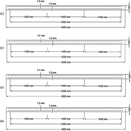
The experimental program consists of testing six beams with overall width, depth and length of 150 mm, 400 mm and 4500 mm respectively, and the beams were simply supported with a clear span of 4200 mm, as shown in . The top longitudinal reinforcement of all specimens was two 10 mm diameter bars. The stirrups were 10 mm diameter bars every 200 mm at middle part of the beams and every 100-mm at edges for a distance 1400 mm from support to middle span of beam, as shown in . shows the prestressing strand had a draped profile similar to the shape of the bending moment produced by acting loads. One strand with diameter 12 mm in addition to two 10 mm diameter bars was used to reinforce the partially prestressed beams. Additional horizontal stirrups were added at anchor zone to resist the splitting force, which is produced at the anchor zone; these stirrups were calculated according to recommendation of the Egyptian code [Citation11]. The variables were considered in this study, concrete compressive strength, and corrosion location effect. As given in . The prestressing strand was placed inside polyethylene duct and fixed with the beam stirrups using horizontal steel chairs. The grouting fitting was placed at distance of 300 mm from each side of beam. The strands were stressed after the concrete had reached an age of 28 days, and then grouted with cementations according to specification instructions.
Fig. 1 Concrete dimensions of tested beam.
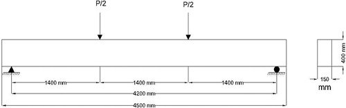
Fig. 2 Reinforcement detail of partially prestressed concrete beams with stirrups distribution along beam length.
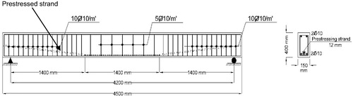
Fig. 3 Prestressed duct profile for 25 mm concrete cover.
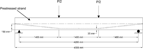
Table 1 Experimental program.
During prestressing, the strand elongation was measured and the prestressing force was recorded. shows the experimentally measured and theoretically calculated force and elongation for partially prestressed beams.
Table 2 Jacking force, initial prestressed force and extension value for theoretical and experimental result for all tested specimens.
Materials properties
Natural siliceous sand and crushed stone had a nominal maximum size of 10 mm. Ordinary Portland Cement (OPC), silica fume, and tap drinking water were used in this work. Also super plasticizer admixture Sikament-163 M and Viscocrete 20 HE were used. The admixture complies with the ASTM C 494 type A and F. Testing of these materials was carried out according to Egyptian Standard Specifications and the ASTM Standards.
Deformed high grade steel bars of 10 mm diameter with yield strength of 470 N/mm2 and ultimate strength of 610 N/mm2 were used as stirrups and longitudinal tension and compression reinforcement. Steel bars were tested and comply with Egyptian Standard Specifications [Citation11].
Fabrication of tested beams
The specimens were fabricated at two stages. The first stage was the casting of six partially prestressed concrete beams, and the second stage was the corrosion technic of four beams. Two concrete mixes were produced with target compressive strength of 40 and 80 MPa after 28 days. The concrete mix proportions are illustrated in .
Table 3 Mix design proportions.
Concrete was cast in the material laboratory of Housing and Building National Research Center at 25 °C temperature. Concrete was compacted after casting using an electrical vibrator for two minutes. The sides of the form were removed after 48 h. Curing of specimens started immediately after casting for 7 days.
Accelerated corrosion technique
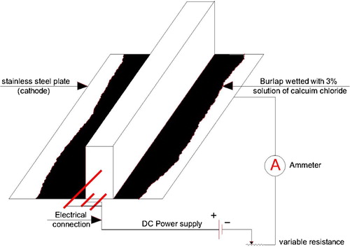
The first phase of the tests was speeding up the rate of corrosion of the steel reinforcement in order to induce deterioration of the partially prestressed beams concrete. Therefore, four partially prestressed concrete beams were subjected to the electrochemical accelerated corrosion technique. The corrosion setup consisted of the test specimen, stainless steel plates (acting as an artificial cathode), and a wet medium between the stainless steel plate and the beams, and a D.C. power supply. The wet medium was burlap wetted by 3% NaCl solution. It should be noted that the cathode stainless steel plate was mounted along regular cross section beam as shown in . The value of the applied current intensity was about 10 μA/mm2 for all of the corroded specimens. This value is considered appropriate for accelerated corrosion tests and has been successfully used by several researchers [Citation4,Citation5,Citation8–Citation10]. The applied current was maintained constant for all specimens by using a variable resistance and was monitored by means of an ammeter.
Fig. 4 The drainage system that keeps the media wet for transporting the electrical field in the samples.
The corrosion level degree was changed from rough to smooth surface. In this research, it was used the mild degree of corrosion. To achieve this degree of corrosion, the specimens were subjected to the corrosion setup for 120 days.
Test setup
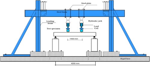
The beams were subjected to two concentrated loads at 700 mm from mid span using two hydraulic jacks of 800 kN capacity. The loads were measured using a load cell of 800 kN capacity, as shown in . The beams were tested up to failure using a stroke control system. The data were collected using a data acquisition system and “a lab view” software at a rate of 1 record per second. The specimen was supported over two concrete blocks of 1400 mm height using one free rod to simulate a roller support and restrained rod to simulate a hinged support.
Fig. 5 Test setup for tested beams.
Instrumentation
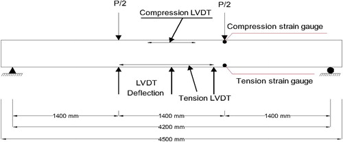
The longitudinal strains of specimens were measured by two different methods: linear variable differential transducers, (LVDT), and electric strain gauges. The strains of concrete and non-prestressed steel reinforcement were measured in the longitudinal direction. Deflection was measured at mid-span and under the concentrated loads. shows location of different instrumentations.
Fig. 6 Location of different instrumentations for tested beams.
Experimental results and analysis
The measured cracking, yielding, ultimate load capacities and the corresponding deflections of each beam are presented in . Ductility, initial stiffness and post cracking stiffness of each beam are presented in .
Table 4 Results of cracking, yielding, ultimate load capacities and the corresponding deflections of tested specimens.
Table 5 Results of ductility, initial stiffness and post cracking stiffness of tested specimens.
Where:
| (1) | Ductility is defined with the ratio of area under load deflection curve at ultimate load to area under load deflection curve at yield load. | ||||
| (2) | Ki: initial stiffness calculated by slope of the load deflection curve before cracking. | ||||
| (3) | Ku: post cracking stiffness calculated by slope of the load deflection curve after cracking up to yielding of reinforcement. | ||||
Application of the statically based approach to the corroded rebars of the test partially prestressed concrete beams
The statically based approach presented by EL-Hefnawy [Citation5] can be used to estimate the residual minimum cross sectional area of the corroded rebar from three random diameter measurements, and this approach can be applied to the corroded rebar of the partially prestressed beam tested through the experimental part of the current research work. lists the estimated minimum cross sectional area of each rebar of the corroded test partially prestressed beam using the statically approach presented by EL-Hefnawy [Citation5].
Table 6 The estimated minimum cross sectional area.
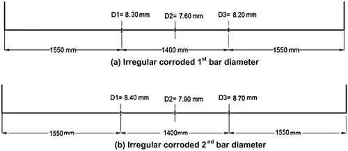
In an attempt to verify the accuracy of EL-Hefnawy [Citation5] statically model for estimating the minimum area of corroded rebar from measuring three random diameters along the corroded rebar length, the actual minimum bar diameters were determined for all corroded rebar of the tested beams. Hence the actual minimum cross sectional area of corroded rebar can be computed. The actual minimum cross sectional area of all corroded rebars of the tested beams is shown in Figs. –.
Fig. 7 Irregular corroded bars diameter for specimen B2. (a) Irregular corroded 1st bar diameter. (b) Irregular corroded 2nd bar diameter.
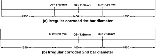
Fig. 8 Irregular corroded bars diameter for specimen B3. (a) Irregular corroded 1st bar diameter. (b) Irregular corroded 2nd bar diameter.
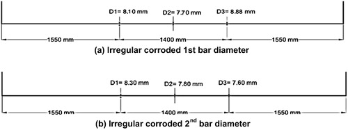
Fig. 9 Irregular corroded bars diameter for specimen B5. (a) Irregular corroded 1st bar diameter. (b) Irregular corroded 2nd bar diameter.
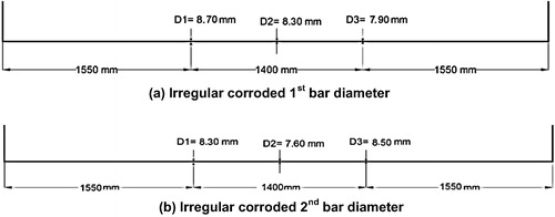
Fig. 10 Irregular corroded bars diameter for specimen B6. (a) Irregular corroded 1st bar diameter. (b) Irregular corroded 2nd bar diameter.
Effect of percentage of steel reinforcement
To investigate the effect of percentage of steel reinforcement on the corroded and non-corroded partially prestressed beams, shows the ultimate loads and the reduction percentage in load carrying capacities due to corrosion of partially prestressed concrete beams having the same characteristics except the percentage of steel reinforcement.
Table 7 Effect of percentage of steel reinforcement on partially prestressed beams capacities.
Corrosion-induced cracking
For samples B2, and B5, both of the non prestressed steel and prestressed tendon were exposed to corrosion at the same time, for the same duration and under the same conditions as the remaining corroded beams. The deterioration in bonded prestressed tendon is less likely to occur due to complete filling of grout in the plastic duct. Conversely, the deterioration in non prestressed steel reinforcement bars was more likely to corrode due to being exposed to all corrosion conditions “such as; PH level, chemical attack, and chloride penetration” without any protection as opposed to a protected bonded prestressed tendon. The corrosion in bonded prestressed tendons is generally due to incomplete filling of the duct “i.e. lack of grout in contact with tendon” or to penetration of chloride through defects of the sheath. Small hairline cracks can be observed also at anchorage zone for B2 due to corrosion of anchorage hardware or anchorage plate which can lead to cracking and spalling of concrete near the anchorage and continued corrosion.
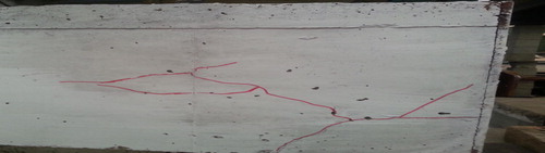
As for samples B3 and B6, only the non prestressed steel was exposed to corrosion; however, the partially exposed samples were exposed at the same time, for the same duration and under the same conditions as the remaining corroded beams. Due to the accelerated corrosion process of the beam steel reinforcement, cracks were observed on the bottom and side surface of the beam. The corroded beam displayed horizontal cracks at positions of main longitudinal steel reinforcement. The reason for this was the accumulation of corrosion products that increased the volume of reinforcement and hence developed extensive stress on the surrounding concrete. These stresses forced the concrete cover to crack. shows the mapping of corrosion Induced cracks for specimens B2, B3, B5, and B6 respectively.
Fig. 11 Mapping of stress crack corrosion for specimens (B2, B3, B5, and B6).
Modes of failure and cracking pattern
shows the failure modes and cracking pattern of partially prestressed concrete beams with compressive strength of 40 and 80 MPa.
Fig. 12 Crack pattern and failure for specimens.
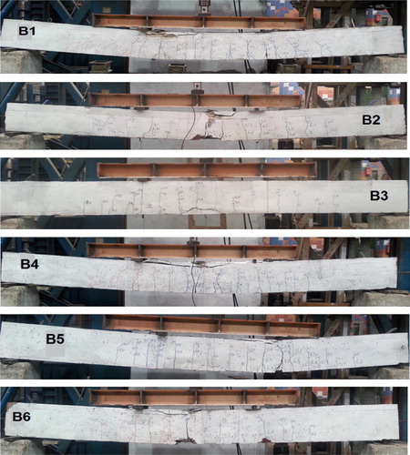
In general, failure of all partially prestressed specimens started by yielding the main bottom steel reinforcement followed by crushing the concrete at the top surface. At onset of concrete crushing, the top reinforcement buckled and the stirrups were exposed. The prestressing tendon yielded as the load was increased gradually, and the rupture occurred first for non prestressed steel followed by the rupture of the prestressing tendon. The following are summarized as can be seen in the previous figures:
| 1. | Modes of failure of partially prestressed concrete beam with normal compressive strength were more ductile than those of partially prestressed concrete beam with high compressive strength. This is attributed to the grade of concrete compressive strength. | ||||
| 2. | The crack pattern for partially prestressed concrete beams is distributed along their entire length and has a small crack width and high number due to the grade of compressive strength of the concrete beams. | ||||
| 3. | The crack pattern of the partially prestressed beams of 80 MPa compressive strength in region between the two concentrated loads was distributed along this length with larger width and fewer numbers than that observed in partially prestressed beams with 40 MPa. | ||||
The cracking pattern for beams exposed to corrosion was similar to the control beams, in addition to the following observations:
| 1. | The concrete color of the beams subjected to corrosion turned to brown, at the corrosion rebar zone as shown . | ||||
| 2. | Irregular cracks at concrete cover with various thickness have appeared along the beam length as shown . | ||||
| 3. | Hairline cracks at anchorage zone for B2 as shown in . | ||||
Fig. 13 The deterioration of the concrete against corroded rebar for samples.
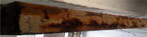
Fig. 14 Hair crack at anchorage zone.
Discussion
In general, exposure to corrosion for all specimens at the same time duration and condition along 120 days reduced the flexural capacity of the partially prestressed beams of 40 MPa compressive strength fully exposed to corrosion by 17% and those partially exposed to corrosion decreased by 14%; this is shown in . The initial stiffness of the control beam B1 was 32% and 26% higher than that of beam B2 (fully exposed to corrosion) and beam B3 (partially exposed to corrosion), respectively. The ductility of the control beam B1 was 13% and 9% higher than that of beams B2 and B3, respectively as shown in . These differences in the stiffness and ductility are attributed to corrosion of steel.
Fig. 15 Load-mid span deflection relationship for B1, B2, and B3.
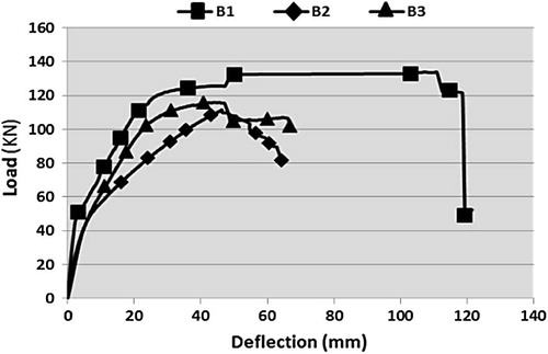
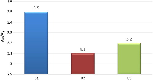
Fig. 16 Ductility of partially prestressed beams with 40 MPa compressive strength.
Exposure to corrosion reduced the flexural capacity of the partially prestressed beams B5 (fully exposed to corrosion) and B6 (partially exposed to corrosion) of 80 MPa compressive strength by 15% and 13%, respectively as shown in . The initial stiffness of the control beam B4 was 25% and 16% higher than that of beams B5 and B6, respectively. The ductility of the control beam B4 was 20% and 12% higher than that of beams B5 and B6, respectively as shown in . These differences in the stiffness and ductility are attributed to the steel corrosion.
Fig. 17 Load-mid span deflection relationship for B4, B5, and B6.
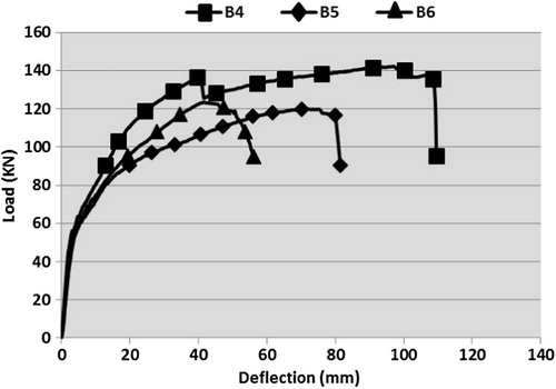
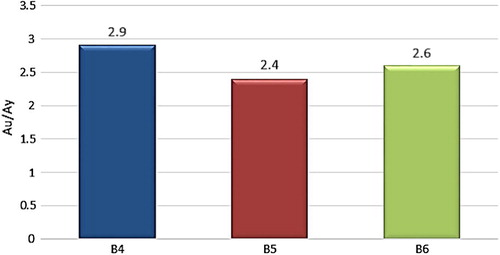
Fig. 18 Ductility of partially prestressed beams with 80 MPa compressive strength.
The abilities of high strength concrete to resist the corrosion are higher than those of the ordinary strength concrete in terms of flexural capacity, initial stiffness, and stress crack corrosion. This is attributed to using highly denies concrete, which leads to low permeability, excellent durability and high performance concrete. This is achieved by the addition of pozzolanic materials “silica fume, fly ash, etc.” that prevents chloride diffusion, and increased from concrete tendency to resist the corrosion. The decreasing of ductility for partially prestressed concrete beams with 80 MPa compressive strength was compared with that of partially prestressed concrete beam with 40 MPa compressive strength which may be attributed to the brittleness of high strength concrete.
The difference in flexural capacity between the fully and partially corrosion exposed for prestressed concrete beams of 40 MPa compressive strength was 4%, while difference between the corresponding 80 MPa compressive strength partially and fully exposed prestressed concrete beams was 3%. This slight difference can be attributed to the damage of the bonded prestressed strands against the corrosion not being observed. This is due to the fact that use of grout to completely fill the gaps around the prestressed strands inside plastic duct prevents the chemical attack and chloride penetration.
The anchorages and end stubs of strands should be carefully protected. Although anchorage corrosion can lead to failure of the anchorage, the bond between the tendon and concrete will prevent a complete loss of pre-stress force. Corrosion of the anchorage hardware, whoever can lead to cracking and spilling of the concrete near the anchorage and also allow moisture to enter the duct causing subsequent tendon corrosion.
Analytical study
Analysis of the tested specimens was carried out to predict the deformational behavior of partially prestressed normal/high strength concrete beams. Deflection and curvatures at the mid-span sections were calculated. Concrete was modeled using a parabolic stress–strain curve, while steel was modeled using a bi-linear stress–strain relationship. Strain compatibility and force equilibrium were carried out using an iterative process to establish the moment–curvature relationship at each section. For each load increment, the curvature at different sections along the length of the beam was determined. Maximum deflection of the beam was calculated by integration of the curvature from the support section to the mid-span section under the specified incremental load. The stress–strain relationship for the strands is taken into account according to the formula presented by Tadros and Devalapura [Citation12].(1)
(1) where
= stress in the steel strand;
A = 384, B = 27,616, C = 119.7, and D = 6.43 (formula constants).
According to EL-Hefnawy approach to use the proposed computer program, some site measurements must be first determined, select three different positions along the rebar length and measure the diameter at each of these positions as shown previously in Figs. –, and used to estimate the probable minimum area of the corroded rebar (AF) as shown in the following formula and used as input data on analytical program [Citation5]:
| a. | Compute the mean and the standard deviation for the three areas for which the diameters were measured (R(x)). | ||||
| b. | Compute the derived mean and the derived standard deviation. The derived mean = U = AR | ||||
| c. | Compute the coefficient of variation | ||||
| d. | Calculate the partial safety factor | ||||
| e. | Calculate the characteristic area | ||||
| f. | Finally, calculate the probable minimum area of the corroded rebar | ||||
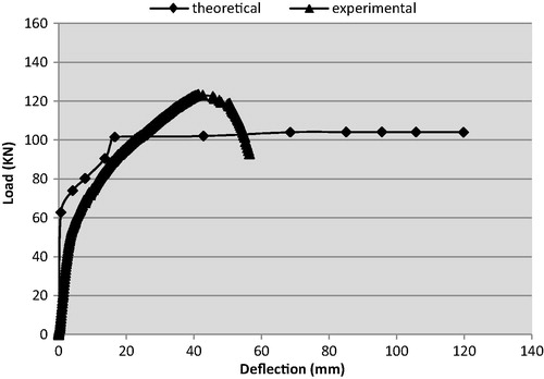
A very good correlation between the predicted and measured behavior was observed and presented in Figs. –.
Fig. 19 Theoretical and experimental result of load–deflection curve for sample B1.
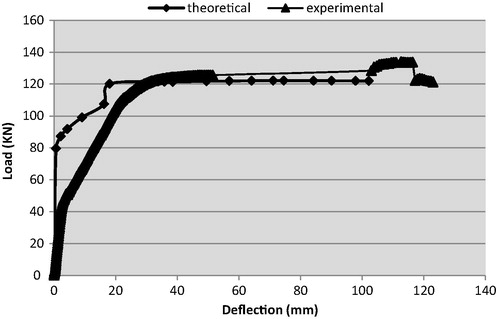
Fig. 20 Theoretical and experimental result of load–deflection curve for sample B2.
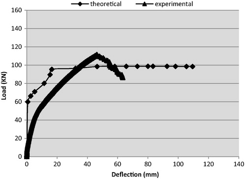
Fig. 21 Theoretical and experimental result of load–deflection curve for sample B3.
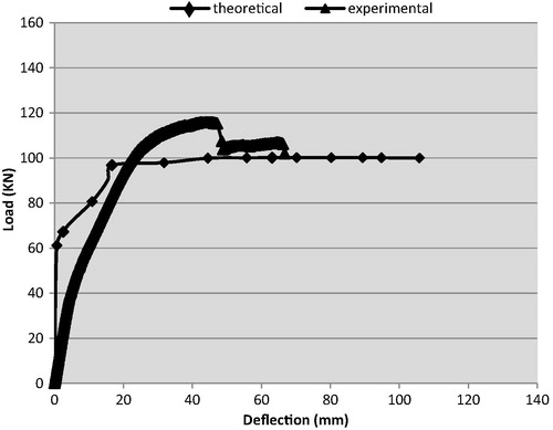
Fig. 22 Theoretical and experimental result of load–deflection curve for sample B4.
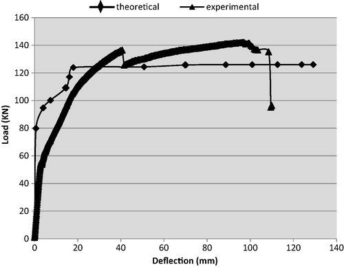
Fig. 23 Theoretical and experimental result of load–deflection curve for sample B5.
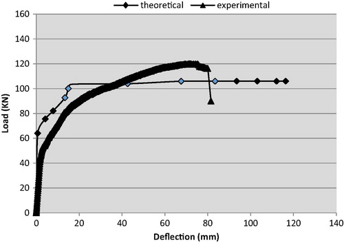
Fig. 24 Theoretical and experimental result of load–deflection curve for sample B6.
Conclusions
From the analysis and discussion of the test results obtained from this research, the following conclusions can be drawn:
| 1. | The increase of the compressive strength from 40 MPa to 80 MPa for bonded partially prestressed concrete beams led to a slight increase in the ultimate flexural capacity and initial stiffness due to corrosion by up to 7.62%, and 11.30% respectively. These are attributed to the increase of concrete compressive strength. Also, the non-uniform hair cracks width as the result of stress crack corrosion, which were observed in high strength concrete beams, is smaller than that in ordinary strength concrete. | ||||
| 2. | The increase of the compressive strength from 40 MPa to 80 MPa for bonded partially prestressed concrete beams leads to a decrease in the ductility due to corrosion up to 22.58%. This decrease in ductility may be attributed to the brittleness of high strength concrete as opposite to ordinary strength concrete. Partially prestressed concrete beam with ordinary compressive strength was developed. Well distributed cracks along their span were smaller in width and bigger in number than those of partially prestressed concrete beams with high strength concrete. | ||||
| 3. | The most of deterioration incident in partially prestressed beam acts on non prestressed steel reinforcement. Because the bonded tendons are less likely to corrode, occurrence of corrosion for bonded prestressed steel strand is so complex and influenced by many factors. This is often referred to as providing multilevel protection for prestressed strand; cement grout is a barrier to moisture and chloride penetration and produces an alkaline; duct works as a barrier to moisture and chloride especially plastic duct without splices and connections. It is preferred to use of more protection methods for non-prestressed steel bars such that epoxy painting or complete filing of grout in the plastic duct like prestressed strand. | ||||
| 4. | The theoretical analysis based on strain compatibility and force equilibrium gave a good prediction of the deformational behavior for partially prestressed concrete beams with high and normal compressive strength. | ||||
Notes
Peer review under responsibility of Housing and Building National Research Center.
References
- F.H. Omnia, Behavior of Fully and Partially Prestressed Concrete Beams with Different Compressive Concrete Strength. Ph.D Thesis, Ain Shams University, 2012.
- O.F.HussienT.H.K.ElafandyA.A.AbdelrahmanS.A.Abdel BakyE.A.NasrBehavior of bonded and unbonded prestressed normal and high strength concrete beamsHBRC J.82012239251
- A.M. Ismail, Behavior of Statically Determinate Prestressed Concrete Beams Subjected to Fire. PHD. Thesis, University of Ain Shams, 2011.
- A.A. EL-Hefnawy, Some Durability Aspects of Concrete in Absence of Silica Fume. MSc. Thesis, Cairo University, 1995.
- A. El-Hefnawy, A New Statistical Approach for Predicting the Residual Capacity of Reinforced Concrete Beams Having Corroded Main Steel. Ph.D. Thesis, Cairo University, 2000.
- International Standard, Statistical Methods for Quality Control of Building Materials and Components, ISO 12491:1997 (E), first ed., Switzerland, May, 1997.
- E.GestsdottirT.GudmundssonBond Behavior of Naturally Corroded Reinforcement in Concrete Structures Master of Science Thesis in the Master’s Program Structural Engineering and Building Performance Design2012CHALMERS University of Technology GöteborgSweden
- T.S.AL-AttarM.S.Abdul-kareemEffect of chloride ions source on corrosion of reinforced normal and high performance concreteBuletinul AGIR022011107112
- M. Khafaga, T. Bahaa, structural behavior of reinforced concrete beams deteriorated due to corrosion of web reinforcement, in: International Conference: Future Vision and Challenges for Urban Development Cairo, Egypt, 20–22 December 2004.
- A. Elgabry, M. Hilal, H. Bahnasawy, M. El-Attar, Rehabilitation of Corroded Reinforced Concrete Frames Using CFRP Sheets. Structural Composites for Infrastructure Applications, Alexandria, Egypt, May 2005.
- Egyptian Code of Practice for Reinforced Concrete Construction, E.C.P. 2007, Ministry of development, New Communities, Housing and Utilities, Housing and Building National Research Center.
- M.K.TadrosR.K.DevalapuraStress–strain modeling of 270ksi low-relaxation prestressing strandsPCI J.371992100106