
Abstract
This study presents the development of a novel maximum-power point-tracking (MPPT) method based on an input shaping scheme controller. The proposed method that changes the initial input response into a shapeable MPPT algorithm is designed based on an exponential input function. This type of input function is selected because of its capability to stabilize the system at the end of the simulation time and remain at the same condition at the final response time. A comparison of the system with the proposed method and the system with traditional perturb and observe (PnO) method is also provided. Results show that the system with the proposed method produces higher output power than the system with PnO method; the difference is approximately 15.45%. Results reveal that the exponential function input shaper allows the overall output system to exhibit satisfactory behavior and can efficiently track the maximum output power.
1 Introduction
Natural energy-harvesting devices harness environmental energy into useable energy. This approach has made energy harvesting as an important research area and a solution to the environmental pollution caused by the hazardous waste of non-renewable energy sources. However, this type of energy harvester is unpredictable and can exhibit erratic behavior in a data-driven system. Many studies have combined energy from different sources, such as solar-thermal (Chávez-Urbiola et al., Citation2012; Lesage et al., Citation2013; Liao et al., Citation2014; Xiaodong et al., Citation2010; Zhang and Chau, Citation2011"), solar-wind (Tianpei and Wei, Citation2014; Xiangjun et al., Citation2013"), and solar-thermal-vibration (CitationBandyopadhyay and Chandrakasan, 2012). This combination is implemented based on the belief that doing so would increase the overall system efficiency. Many previous studies selected solar energy as the main energy source because this source produces high power. In CitationZhang and Chau (2011), they acclaimed that their newly developed power conditioning system was able to increase the overall hybrid system output power. The combination between the proposed method and the Ćuk–Ćuk converter has proved that both thermoelectric and solar branches can attain the maximum power conversion individually. Furthermore other related works regarding the hybridization between thermoelectric and solar in Dallan et al. (Citation2015), Wu et al. (Citation2015)" has also given extra credit to the development of the hybrid system in the energy harvesting field. However, solar energy only functions when sunlight is available. In addition, heat dissipation and the development cost of solar energy limit the efficiency improvement of this energy source (Jha, Citation2009; Odeh and Behnia, Citation2009"). These circumstances impede the performance of solar energy unless combined with other renewable sources that can take over the task of solar energy when sunlight is unavailable.
In this research, a thermoelectric module (TEM) was employed to boost the performance of solar energy because this device is known to convert the heat dissipation of waste heat energy into electrical energy. This condition occurs when thermal differences exist between the two junctions of the TEM, namely, hot and cold junctions (CitationNguyen and Pochiraju, 2013). However, a TEM cannot function individually because it produces low power. By combining a TEM with solar energy to develop a hybrid energy-harvesting system, the disadvantages of each system can be overcome because these two sources complement each other.
Given that solar energy and TEM are non-linear devices, a DC–DC converter is utilized to extract the maximum power from each system individually. Three main maximum-power point-tracking (MPPT) algorithms, namely, perturb and observe (PnO) (Balato and Vitelli, Citation2014; de Brito et al., Citation2013; Kortabarria et al., Citation2014; Mamarelis et al., Citation2014; Murtaza et al., Citation2014"), incremental conductance (Kumar et al., Citation2014; Tey and Mekhilef, Citation2014"), and impedance matching (CitationYamada et al., 2014), have been adopted in previous studies without focusing on the sources. The PnO algorithm is commonly used in both solar energy and TEM because of its simplicity and ease of design development. Many enhancements on the PnO algorithm have been made in recent research. CitationKortabarria et al. (2014) developed a new PnO method that employs the adaptive intelligent algorithm. However, this newly developed PnO was applied to wind turbines. By concentrating on applying the application solely to solar energy, CitationMamarelis et al. (2014) also focused on PnO algorithm improvement by introducing a two-step algorithm. They confirmed that their proposed method requires simple mathematical calculations. Hybridization of the MPPT method has also been attracting a significant amount of attention recently. In CitationMurtaza et al. (2014), the authors worked with PnO and fractional open-circuit voltage. A hybrid MPPT can make the system focus solely on the maximum power point (MPP) without exhibiting power loss oscillation. Validation is performed under the condition of steady weather. For instance, in CitationBalato and Vitelli (2014), distributed maximum-power point-tracking was developed with rapid tracking and robustness for systems that contain errors.
All the above mentioned PnO methods have been improved either to make the methods work in high speed tracking or increase the sensitivity of the perturbation technique. No previous study has discussed the stability of the overall system behavior. The previous PnO method also involved a complex numerical analyses which need extra time and effort on scrutinize the performance of the improved PnO method. Although the PnO method is known for its easiness in terms of implementation, the oscillations problem caused by this method tends to decrease its accuracy (CitationSahnoun et al., 2013). If this oscillation can be counter back, the output response of this method can become stable. CitationSahnoun et al. (2013) in their paper has proposed a neural technique algorithm to control the PnO method but this method is very complex. In order to improve the previous PnO method by ensuring its stability, a new method must not compromise in any oscillation problem. This method also must be easy to implement so that no complex calculation in maximum power point is issued later on that needs extra effort in this matter.
Thus, a new control method was developed in the present study by combining the PnO method and an input shaper to ensure the overall stability and simplicity of a hybrid energy-harvesting system. The proposed method was designed with improved identification to increase the efficiency of the existing hybrid thermoelectric module and solar array (TEM–SA) and reduce the energy consumption of the system. The input shaper employed in this study is a feed forward control method commonly applied to flexible systems (Sahinkaya, Citation2001, Citation2004") to reduce system vibration. CitationDevasia (2012) employed this method to control the settling time of a positioning system. The input shaper is based on inversion dynamic analysis, which was proposed by CitationPiazzi and Visioli (2000). This approach is implemented by setting a polynomial function as the acquired output function. The method suggested by Piazzi and Visioli is impressive and beneficial in terms of stability. However, the polynomial function at the end point of the validation time exhibits unpredictable behavior and thus limits the application of the method. To overcome this problem, the polynomial function must be switched into a different form. Several methods, such as the Lyapunov function (Wang et al., Citation2014; Xiang and Xiang, Citation2014; Zhang et al., Citation2014; Zhao et al., Citation2014"), dwell time approach (Briat, Citation2014; Xiang et al., Citation2014; Zhang et al., Citation2014"), and sojourn method (Tian et al., Citation2014a,Citationb"), have been discussed recently. With regard to the switching requirement, CitationIravani and Sahinkaya (2010) reported that switching would affect the first and second derivatives of the function and result in the unstable output behavior of the overall system. Hence, in the present work, the stability of the overall system was not based on the switching method. Based on the work of Piazzi and Visioli, several notable solutions that employ an exponential function have been proposed by several other researchers (Iravani and Sahinkaya, Citation2010; Rymansaib et al., Citation2013; Sahinkaya, Citation2001, Citation2004"). This type of function overcomes the drawbacks of the polynomial function. Thus, this type of function was applied in the MPPT circuit in the current study. The proposed method was proven to require minimal mathematical calculation, which eases the MPPT development of the overall system. The proposed method is also capable of efficiently tracking MPP with high efficiency.
2 Modeling of TEM–SA
In a TEM–SA hybrid energy-harvesting system, the systems that correspond to TEM and SA were designed as individual systems. Both systems were then merged to produce a hybrid system. This hybrid model was designed according to the electrical specifications provided by the manufacturers to imitate the performance of the actual device. The hybrid system was designed based on the assumption that the losses caused by the bonding between the multi-stages of TEM and SA are neglected.
2.1 Modeling of TEM
TEM heat was modeled under a dynamic condition, wherein the cold junction for self-cooling was maintained without using any heat sink. This condition was enhanced. The temperature of the cold side was maintained for natural cooling to create a dynamic response because most previous studies have scrutinized steady-state behavior, wherein only constant temperature was considered (CitationNguyen and Pochiraju, 2013). The TEM input temperature varies with time in practical applications.
The most important effect on TEM heat modeling is known as the Seebeck effect. This effect, which is attributed to the voltage difference between the two junctions, occurs when the temperature between two different materials changes. TEM heat was modeled in MATLAB and represented by the electrical properties of TEM. The TEM model (TEP1-12656-0.6) from Thermonamic was selected where the specifications and the MATLAB model have been detailed in (CitationYusop et al., 2013).
2.2 Modeling of SA
A common one-diode model with shunt resistance was utilized to represent the SA model in this design. The characteristics of SA depend on the solar radiation and temperature of the SA surface. Electrical current is produced when SA is exposed to sunlight. When the energy provided by sunlight is greater than the band gap energy of SA, an electron–hole pair is formed. The carriers then produce current that increases with irradiation. The equivalent circuit of the solar cell follows the same circuit in CitationYusop et al. (2014).
To address the importance of the data-driven analysis result, the actual specification of solar module SR10-36 from Raloss where has been listed out in CitationYusop et al. (2014) was utilized to represent the SA model. A similar specification was then included in the MATLAB/SIMULINK model to create an SA module.
The I–V and P–V characteristics of SA depend on the terminal operating voltage, insolation, and surface temperature. These characteristics were obtained by varying insolation at constant temperature or varying temperature at constant insolation. The product of the highest value current, Imp, and highest value voltage, Vmp, produced MPP. To ensure that SA always functions correctly at MPP, the value of Vmp and Imp were controlled to operate at the MPP ratings. This is the point where the MPPT algorithm was added. With the consideration that the hybrid system is expected to have only one MPPT system, the circuit model orientation was applied only to the SA module. The SA model, which was designed in SIMULINK, was then converted into circuit model orientation to make the model equivalent to the actual one (CitationN et al., 2012). The input of the circuit model is the SA current produced by the previous MATLAB model. The output voltage of the circuit model was used again as the voltage input in the MATLAB model. The characteristic of the output voltage of this circuit orientation is expected to be similar to that of common SA. This output voltage was then used as the input to the MPPT system.
3 MPPT system of the TEM–SA hybrid energy system
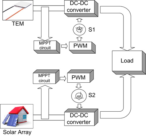
The block diagram of the proposed TEM–SA hybrid energy system consists of six TEMs connected electrically in series and thermally in parallel; two SAs are joined in parallel followed by a DC–DC boost converter with pulse width modulation (PWM) control as shown in . The entire system was connected with a load representing a 50 Ω resistor. The electrical specification of power MOSFET IRFP460 from ST Semiconductors was employed as a switching device (S1 and S2 of the converter). The switching frequency of the PWM signal was set to 20 kHZ, and the voltage of the converter was changed by varying the duty ratio of the PWM signal. The DC–DC boost converter is commonly utilized to increase the low voltage of the system and comply with the load constraint.
Figure 1 DC–DC converter of the hybrid energy-harvesting system to operate at MPP.
3.1 Controller design to implement the shapeable MPPT algorithm
TEM has a more stable output behavior than SA. Therefore, TEM plays the key role because it produces a larger time constant than SA. Consequently, SA can be designed to imitate the behavior of TEM by adding a suitable controller that can shape the characteristic of SA to imitate TEM. The suggested controller transforms the characteristic of SA before being added to the MPPT system. Therefore, the final hybrid output power is believed to have the characteristic of a TEM, including the maximum tracked power.
To reduce the power consumption of the hybrid system, a controller based on feed forward control was utilized in this study together with the existing MPPT algorithm to develop the shapeable MPPT algorithm. The energy consumption of feed forward control is minimal compared with that of other control algorithms. Feed forward control is a type of controller that does not allow large disturbances at the output. One of the requirements that can make feed forward control sufficiently reliable when compared with closed loop control is that the output behavior must be known. The output power gained from feed forward control is the reason this type of controller was included in this design.
The term “shapeable” originates from the controller based on input shaping technique to overcome the limitation of the previous MPPT scheme. By combining the shapeable controller and PnO MPPT scheme, the system was able to imitate the behavior of TEM and obtain the correct MPP. The input shaping technique used in the design is inverse dynamic analysis, which is able to shape the behavior of the hybrid energy-harvesting system to imitate that of TEM. Given that the output behavior is already known, this selected controller is the ideal solution for this design requirement.
The TEM–SA hybrid energy system was implemented in SIMULINK/MATLAB. The controller based on inverse dynamic analysis was applied to the hybrid energy-harvesting system to change the output characteristic of SA. In addition, this controller was only applied to the SA block model. The input shaper was able to control SA behavior without implementing the PnO algorithm because PnO was only applied to the TEM block system. SA has a non-linear characteristic because its output characteristics are affected by various factors, such as temperature and sunlight irradiation. Considering the abovementioned factors, the MPP of this hybrid system must be effectively tracked. In this study, the inverse dynamic analysis exponential type of input shaper was utilized to obtain the input voltage of SA. This was done before merging the input voltage with the MPPT circuit. By selecting this type of input shaper, the output characteristics were selected depending on the system requirements. This input shaper endeavors to reverse the control process by primarily specifying the system output function and subsequently deriving the input function. The meticulous limitation of the system output function is that it obtains the output power reciprocally by controlling the system precincts.
3.2 Inverse dynamic
The inverse dynamic can be added to the input voltage of SA because of the changes in the current behavior when the voltage function is changed. The rule of thumb applied in this study is that the SA power behavior must follow the TEM behavior. Concurrently, the form of the desired output waveform was set before specifying the input function. In the simulation, the SA input voltage was obtained from the output voltage of the SA circuit orientation, which has been designed in Section 2.
The system transfer function for this hybrid energy-harvesting system only focuses on the voltage form and is defined as,(1) where VSA(u) is the SA harvested voltage, F(u) is the normalized input of SA and X(u) is the normalized desired output function. The normalized input was obtained using inverse dynamic by substituting the SA input function and the desired output form in Eq. Equation(1)
(1) . The desired output function needs to be selected before this input function is forming. This function is developed based on exponential function. This is done by picking a suitable order of exponential function that imitates the desired output response.
3.3 Desired output behavior
According to CitationPiazzi and Visioli (2000), asymptotic behavior is required in positioning the ultimate point of the last output behavior and needs remain in the same position. The exponential functions introduced by CitationSahinkaya, (2001) effectively resolve the disadvantages of asymptotic behavior. At this juncture, the third-order exponential function of the output function was assessed to control the system from time = 0 to XE as the target output waveform similar to the first derivative of this exponential function (CitationYusop et al., 2014). The function that represents the point-to-point output characteristic should be differentiable and continuous at least upto a second-order derivative. In addition, the first and second derivatives at the initial and final simulation time points, XE, are both zero and should remain so.
This third-order exponential function is expressed as follows:(2)
To generalize the analysis, normalized time u is defined as follows:(3)
From Eqs. (2) and (3), the normalized equations of the desired output function are obtained as follows:(4)
The derivatives are shown in the following equations.(5)
(6)
The output function together with its derivatives is used to match with the desired output function. In this case, the target output voltage function is similar to the first derivative of the third-order exponential function; thus, X(u) is set to,(7)
By doing this, the desired output function represents the third-order exponential function output response that can be seen detailed in CitationYusop et al. (2014). The desired output function can be one of the exponential function responses or the combination between two or more output functions that is exemplified by Eqs. (4)–(6). The effect of exponential function in this input shaping design is discussed in the following subtopic.
3.4 Exponential input shaping design
In short, the exponential input shaping design, which is based on the input voltage, changes its process from initial behavior to exponential behavior. This type of input function has satisfactory stability at the final point of the simulation behavior. The input function is independently expressed as,(8)
The new output power has a similar behavior as the input voltage. Thus, the total hybrid power achieves the correct MPP, and the SA power behavior imitates the input function. The design process of inverse dynamic analysis has been shown in CitationYusop et al. (2014). The analysis starts by generating the desired output equation of the system. It has been stated before that this function should stay at the final position until the analysis time ends. Next, the input function which includes the exponential function is derived according to Eqs. (1)–(8). After the input function block is located right after the input signal of the SA, the power behavior of the hybrid system is checked whether it follows the TEM behavior or not. If the power behavior of the hybrid system is not similar with the TEM behavior, the input function needs to be recalculated. Then the input function is again added to the input signal of SA and the process repeated. For the other path if the power behavior is similar with the TEM behavior, output response of the overall system is obtained. This output response should be the same with the first initial desired output response that has been selected before exponential input shaping function is designed.
4 Simulation results
Two simulation models were implemented to verify the performance of the hybrid energy-harvesting system after applying the power electronic circuit model. This performance verification included the thermal behavior and electrical properties of the overall system. Moreover, the proposed system was compared with the existing system, which applies the same method of input shaper as the controller.
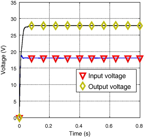
For the first simulation models, the hybrid energy-harvesting system was built together with the power electronic circuit to boost the current voltage to a high value and maintain that value until the end of the simulation. At this part, the PnO algorithm was introduced to both the TEM and SA subsystems to track the maximum power of the overall system efficiently. The input voltage of the TEM originates from the open-circuit voltage of the multi-stage TEMs. The current that flows through the TEMs decreased with the presence of internal resistance. Both subsystems were able to produce maximum power by controlling the duty ratio of the PWM signal. This duty ratio was obtained from the PnO algorithm. The value of the duty ratio was set to 0.3 because this value can stabilize the power behavior of the system. The output voltage of SA increased to 27.88 V from an input voltage of 18.04 V ().
Figure 2 Input and output voltages of SA.
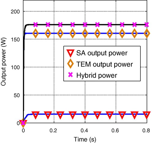
The power level of TEM is greater than that of SA because in the modeling, the open-circuit voltage utilized was obtained based on the specification provided by the manufacturer. The open-circuit voltage was obtained under the condition that the TEM’s hot side temperature is equivalent to 300 °C and its cold side temperature is 30 °C. The hybrid power of the overall system was derived from the summation of TEM and SA power. The settling time, Ts, of SA is less than that of TEM, which means that the TEM response is quicker than that of SA (). Hence, the SA behavior was designed to imitate the TEM behavior.
Figure 3 Output power of TEM, SA, and hybrid TEM–SA.
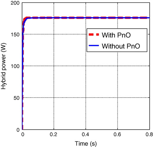
A similar analysis was performed in the second experiment, but the PnO algorithm was no longer employed. The task of the PnO algorithm was replaced by the input shaper to produce the shapeable MPPT algorithm. The results of the hybrid power for the two different analyses are plotted in . From the perspective of hybrid power analysis, both graphs are similarly maintained at 175.84 W. This value is the maximum output power of the overall system. With regard to the system response, the system without the PnO algorithm reacts a bit slower than the other one. Given that the effect is insignificant and the system without the PnO algorithm still performed similar to the system with the PnO algorithm, this disadvantage was ignored. The system with the input shaper was proven to be capable of taking over the PnO task of efficiently tracking the MPP.
Figure 4 Hybrid power of the TEM–SA hybrid energy system.
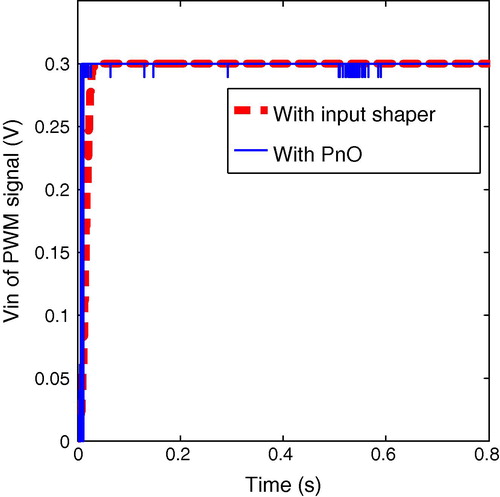
The output response of the input shaper and PnO was then inputted into the PWM block system to produce a suitable PWM signal. The obtained PWM signal was used as the trigger signal to activate the boost converter switch. In the consideration of the input voltage of the PWM block system, the graph of the system with the input shaper tends to have a smoother performance than that of the system with the PnO algorithm (). This result is due to the fact that in the PnO method, the voltage and current are perturbed by a certain point of increment, and the change in power, ΔP, is compared with MPP for each reading. This phenomenon is the reason the graph appears to be disorganized at certain points, especially at the starting point. By using the input shaper, the graph with an exponential type of behavior was established because this type of graph was introduced as the main function of the input shaper. As discussed in Section 3.4, exponential-type behavior is the ideal solution for any system because of the relaxation at the final point.
Figure 5 Input voltage of the PWM signal.
The merits of the proposed shapeable MPPT algorithm are clearly emphasized in the following statements.
| (1) | The findings show that the proposed method can take over the task of the PnO algorithm and is superior over other types of MPPT algorithms because the proposed method performs very well in any condition of voltage or current. This observation is attributed to the performance of the response, which can follow only one behavior, that is, the exponential function. | ||||
| (2) | Another advantage of the proposed method is its ability to react to the desired output behavior by selecting only a suitable signal response that can imitate the overall system response. By introducing an appropriate input response, designing different controllers and MPPTs for both TEM and SA before developing a hybrid energy-harvesting system would be easy. | ||||
| (3) | The potential of the inverse dynamic input shaper to abruptly change the response signal to follow the exponential behavior initially stabilized the system and allowed it to produce a good response at the maximum output power. This solution provides additional support for energy-harvesting research, in which the MPPT circuit is widely utilized. The plotted graph in specifically relates to this observation. | ||||
| (4) | Comparison with existing studies was also performed to validate the performance of the proposed method. The input voltage of the PWM signal obtained from the implementation of the proposed method agrees well with the characteristics of the same method applied to a flexible system in CitationSahinkaya (2001). The difference between these two studies is reflected on the peak value and system response (whether fast or slow). In CitationSahinkaya (2001), the peak value of the response is 1, whereas in the current work, the peak value of the response is 0.3. Initially, the peak value of the response obtained the same value as that in previous studies. However, the design system in the present work needs to initialize the PWM signal in a fixed value of 0.3 V; hence, the response was changed to this required condition. This result shows that the input shaper based on the exponential function is able to react in the same manner as that in an energy-harvesting system. The system response in the current work is faster than that in previous studies because previous studies are limited by system displacement, velocity, and acceleration. Hence, the authors need to include parameter β, which relates system speed and speed of motion. In an energy-harvesting system, this parameter is ignored because of the elimination of the limitation in system speed. | ||||
| (5) | Compared with the method proposed by CitationMamarelis et al. (2014), the method proposed in the current study requires less mathematical calculation and design steps to perturb the voltage. | ||||
| (6) | The system with the proposed method can produce higher output power; the difference between the proposed method and the PnO algorithm is approximately 15.45%. | ||||
The effectiveness of the exponential function input shaper when applied to the TEM–SA hybrid energy system is sufficient after the MPPT circuit is applied. The recognition of the proposed method in the field of energy-harvesting systems can narrow down the implementation of complicated MPPT algorithms.
5 Conclusion
A complete MPPT algorithm that considers the electrical properties of the TEM–SA hybrid energy-harvesting system was fabricated through MATLAB/SIMULINK. This MPPT algorithm was employed based on the exponential function of the input shaper, which is capable of obtaining correct MPP and meets the system constraints. To overcome the model performance limitation in the steady-state condition, the model was purely designed to handle transient analysis. Simulation results show that the proposed controller algorithm can control the output behavior of the overall system. A satisfactory hybrid output power curve was attained at the end of the simulation. In addition, this algorithm abridges the control of the entire system; the controller was designed such that SA behavior imitates the TEM behavior. The energy consumption of the system decreased by controlling only the input behavior based on a feed forward scheme. Notable consequences were observed when the input shaper was utilized. The inverse dynamic input shaper was developed in built-in control blocks, and the MPPT circuit was designed using SimPowerSystem tools in MATLAB.
Conflict of interest
None.
Acknowledgments
The authors would like to thank the Department of Electrical, Electronic and Systems Engineering, Faculty of Engineering and Built Environment, Universiti Kebangsaan Malaysia, Universiti Teknikal Malaysia Melaka, and the Ministry of Higher Education for the moral, operational, and financial support they provided.
Notes
Peer review under responsibility of University of Bahrain.
References
- M.BalatoM.VitelliA new control strategy for the optimization of distributed MPPT in PV applicationsInt. J. Electr. Power Energy Syst.622014763773
- S.BandyopadhyayA.P.ChandrakasanPlatform architecture for solar, thermal, and vibration energy combining with MPPT and single inductorIEEE J. Solid-State Circuits47201221992215
- C.BriatConvex lifted conditions for robust -stability analysis and -stabilization of linear discrete-time switched systems with minimum dwell-time constraintAutomatica502014976983
- E.A.Chávez-UrbiolaY.V.VorobievL.P.BulatSolar hybrid systems with thermoelectric generatorsSol. Energy862012369378
- B.S.DallanJ.SchumannF.J.LesagePerformance evaluation of a photoelectric–thermoelectric cogeneration hybrid systemSol. Energy1182015276285
- M.A.G.de BritoL.GalottoL.P.SampaioG.de Azevedo e MeloC.A.CanesinEvaluation of the main MPPT techniques for photovoltaic applicationsIEEE Trans. Industr. Electron.60201311561167
- S.DevasiaTime-optimal control with pre/post actuation for dual-stage systemsIEEE Trans. Control Syst. Technol.202012323334
- P.IravaniM.N.SahinkayaVariable-velocity exponential input shaping for position controlled robotic systemsIn: 3rd Annual Dynamic Systems and Control Conference2010University of Bath
- A.R.JhaSolar Cell Technology and Applications2009cRC press
- I.KortabarriaJ.AndreuI.Martínez de AlegríaJ.JiménezJ.I.GárateE.RoblesA novel adaptative maximum power point tracking algorithm for small wind turbinesRenewable Energy632014785796
- K.K.KumarR.BhaskarH.KotiImplementation of MPPT algorithm for solar photovoltaic cell by comparing short-circuit method and incremental conductance methodProcedia Technol.122014705715
- F.J.LesageR.PelletierL.FournierÉ.V.SempelsOptimal electrical load for peak power of a thermoelectric module with a solar electric applicationEnergy Convers. Manage.7420135159
- T.LiaoB.LinZ.YangPerformance characteristics of a low concentrated photovoltaic–thermoelectric hybrid power generation deviceInt. J. Therm. Sci.772014158164
- E.MamarelisG.PetroneG.SpagnuoloA two-steps algorithm improving the P&O steady state MPPT efficiencyAppl. Energy1132014414421
- A.MurtazaM.ChiabergeM.D.GiuseppeD.BoeroA duty cycle optimization based hybrid maximum power point tracking technique for photovoltaic systemsInt. J. Electr. Power Energy Syst.592014141154
- P.NR.RR.MuthuApplication of circuit model for photovoltaic energy conversion systemInt. J. Photoenergy2012
- N.Q.NguyenK.V.PochirajuBehavior of thermoelectric generators exposed to transient heat sourcesAppl. Therm. Eng.51201319
- S.OdehM.BehniaImproving photovoltaic module efficiency using water coolingHeat Transfer Eng.302009499505
- A.PiazziA.VisioliMinimum-time system-inversion-based motion planning for residual vibration reductionIEEE/ASME Trans. Mechatron.520001222
- Z.RymansaibP.IravaniM.N.SahinkayaExponential trajectory generation for point to point motionsIEEE/ASME Int. Conf. Adv. Intell. Mechatron. (AIM)2013906911
- M.SahinkayaInput shaping for vibration-free positioning of flexible systemsProc. Inst. Mech. Eng. Part I: J. Syst. Control Eng.2152001467481
- M.SahinkayaInverse dynamic analysis of multiphysics systemsProc. Inst. Mech. Eng. Part I: J. Syst. Control Eng.21820041326
- M.A.SahnounH.M.R.UgaldeJ.-C.CarmonaJ.GomandMaximum power point tracking using P&O control optimized by a neural network approach: a good compromise between accuracy and complexityEnergy Procedia422013650659
- K.S.TeyS.MekhilefModified incremental conductance MPPT algorithm to mitigate inaccurate responses under fast-changing solar irradiation levelSol. Energy1012014333342
- E.TianW.K.WongD.YueRobust control for switched systems with input delays: a sojourn-probability-dependent methodInf. Sci.2014
- E.TianD.YueT.-C.YangAnalysis and synthesis of randomly switched systems with known sojourn probabilitiesInf. Sci.2772014481491
- Z.TianpeiS.WeiOptimization of battery-supercapacitor hybrid energy storage station in wind/solar generation systemIEEE Trans. Sustainable Energy52014408415
- Y.-E.WangX.-M.SunZ.WangJ.ZhaoConstruction of Lyapunov–Krasovskii functionals for switched nonlinear systems with input delayAutomatica50201412491253
- Y.-Y.WuS.-Y.WuL.XiaoPerformance analysis of photovoltaic–thermoelectric hybrid system with and without glass coverEnergy Convers. Manage.932015151159
- M.XiangZ.XiangExponential stability of discrete-time switched linear positive systems with time-delayAppl. Math. Comput.2302014193199
- M.XiangZ.XiangH.R.KarimiAsynchronous L1 control of delayed switched positive systems with mode-dependent average dwell timeInf. Sci.2782014703714
- L.XiangjunH.DongL.XiaokangBattery energy storage station (BESS)-based smoothing control of photovoltaic (pv) and wind power generation fluctuationsIEEE Trans. Sustainable Energy42013464473
- Z.XiaodongK.T.ChauC.C.ChanS.GaoAn automotive thermoelectric–photovoltaic hybrid energy systemIEEE Veh. Power Propul. Conf. (VPPC)201015
- K.YamadaH.MatsuhisaH.UtsunoImprovement of efficiency of piezoelectric element attached to beam based on mechanical impedance matchingJ. Sound Vib.33320145279
- A.YusopR.MohamedA.AyobA.MohamedDynamic modeling and simulation of a thermoelectric-solar hybrid energy system using an inverse dynamic analysis input shaperModell. Simul. Eng.2014 13
- A.M.YusopR.MohamedA.AyobModel building of thermoelectric generator exposed to dynamic transient sourcesIOP Conference Series: Materials Science and Engineering2013IOP Publishing012015
- H.ZhangD.XieH.ZhangG.WangStability analysis for discrete-time switched systems with unstable subsystems by a mode-dependent average dwell time approachISA Trans.2014
- J.ZhangZ.HanF.ZhuX.ZhaoAbsolute exponential stability and stabilization of switched nonlinear systemsSyst. Control Lett.6620145157
- X.ZhangK.ChauAn automotive thermoelectric–photovoltaic hybrid energy system using maximum power point trackingEnergy Convers. Manage.522011641647
- X.ZhaoX.LiuS.YinH.LiImproved results on stability of continuous-time switched positive linear systemsAutomatica502014614621