
 ?Mathematical formulae have been encoded as MathML and are displayed in this HTML version using MathJax in order to improve their display. Uncheck the box to turn MathJax off. This feature requires Javascript. Click on a formula to zoom.
Abstract
The quest for quality brake pads for use in aircrafts and automobiles to ensure effectiveness and safety continues to attract attention. Hence, this study was carried out as part of the global efforts at tackling the problem of the low durability of these friction materials. An iron millscale (IMS) particle reinforced ceramic matrix composite (CMC) was developed by the powder metallurgy method and characterised. The IMS particle addition varied from 5–30 wt.% in each CMC produced at different particle size distributions (106–250 μm) using silica (SiO2), magnesia (MgO), and sodium bentonite as matrices. On the basis of the close correlation between structure and property, the CMCs were subjected to physical, mechanical, and microstructural characterisation using X-ray Fluorescence (XRF), X-ray Diffraction (XRD), and Scanning Electron Microscopy with Energy Dispersive Spectroscopy (SEM/EDS). The composite exhibits desirable physical and mechanical properties in terms of density (2.97 g/cm3), porosity (1.24%), linear shrinkage (1.39%), impact energy (43.07 J), and compressive strength (114.17 MN/m2). These values compare very well with the values of brake pads obtained in previous studies and conventional/commercial brake pads, indicating a potential for effective performance in service.
1 Introduction
In an attempt to affect significant improvement in the functional characteristics of brake pads for aircrafts and automobiles, different materials have been used, and this has resulted into the development of different types of brake pads [Citation1–Citation4]. However, these brake pads are still known to be plagued by performance related issues, such as wear, thermal instability, warpage and low durability [Citation5]. The quest for quality brake pads cannot be divorced from the development of appropriate advanced materials with superlative characteristics [Citation6].
This explains why friction materials that are used in brake pad components are usually heterogeneous. They are meant to demonstrate improved wear resistance at low and high temperatures, rigidity, and durability and to make less noise. Thus, during production, formulations are made by varying the weight percentages of the constituent materials in a manner that gives rise to an effective modification in the structure, physical and mechanical properties of the brake pad component [Citation1].
The physical characterisation of a material is one of the scientific techniques that is normally employed to investigate its intrinsic properties for potential areas of application. The technique is also often used to isolate potent elements/compounds in a material for optimum utilisation. Such a discovery is meant to guide the appropriate processing method to which the material is amendable and that will best induce desirable characteristics. Thus, preliminary subjection of materials to relevant physical characterisation using appropriate technology is imperative. This is more germane when such materials are being considered for advanced applications.
Ceramic matrix composites with dispersed metallic particles are one class of promising materials for high performance applications under severe environments, such as high temperature [Citation7]. These materials offer the possibility of combining heat resistance, degradation resistance, and wear resistance due to the ceramic phase having high mechanical strength and thermal conductivity being provided by the metallic phase [Citation8]. Thus, ceramic metal composites (CMCs) are currently candidates for functionally graded materials developed for multiple functions at reduced cost [Citation9]. They are used as functional components in brake assemblies, jet fighters, furnace materials, energy conversion systems, gas turbines, heat engines, etc.
This paper focuses on the development, physical, and microstructural characterisation of iron millscale reinforced hybrid ceramic composite with a view of determining its suitability for aircraft brake pad applications.
2 Methodology
2.1 Materials
The reinforcement material used in this study is iron millscale particles, while the hybrid matrices are silica sand, magnesia, and bentonite clay. Iron millscale particles were sourced from Universal Steel Nigeria Limited located in Ogba, Lagos. Silica sand was obtained from the beach of the Lagos Atlantic Ocean (bar beach). Magnesia and bentonite clay powders were obtained from a local vendor within the chemicals supplier trade group registered in Nigeria, but they were manufactured in China and Wyoming, USA, respectively.
2.2 Materials characterisation
The elemental composition and phases present in the materials were determined using an X-ray Fluorescence (XRF) spectrometer (model, ARL9400XP+ Thermo, Switzerland) and an X-ray Diffractometer (model GBC Enhanced Material Analyser, Australia), respectively.
2.3 Hybrid ceramic composite production
2.3.1 Materials milling and blending
Iron millscale was milled using a steel ball mill (model A50 43, Mashine, France) and sieved to a particle size distribution of 106–250 μm using standardised sieves (BSS). The matrix containing 212 μm silica sand, 53 μm magnesia, and 15 μm bentonite was separately mixed with the iron millscale particles, and clean water amounting to 12 wt.% of the total mixture was added. By manual mixing, a uniform distribution of reinforcement particles in the matrix blend was achieved and 80 g the wet blended materials were fed into metallic moulds ().
Table 1 Materials formulation.
2.3.2 Compaction
The Green samples were obtained by uniaxial cold pressing (330 KN/m2) using a hydraulic press (Capacity 100T, Type P100 EH, Model No. 38280, Weber Hydraulik, Germany) to enhance the surface smoothness of the samples. A small amount of lubricant was rubbed on the inner part of the moulds as a releasing agent for easy discharge of the samples from the moulds after compaction.
2.3.3 Drying and sintering
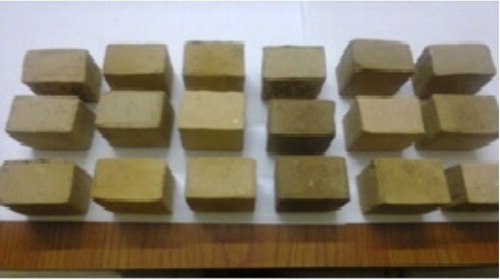
The samples were dried in open air for 3 days, followed by drying under controlled humidity using an oven dryer at 110 °C for 24 h to expel any moisture left in the composite and to avoid cracking during sintering. To facilitate the bonding of powder particles (vitrification), the compacted samples were gradually heated to temperatures below the melting point of the materials but high enough to develop significant solid state diffusion. Sintering was carried out in a heat treatment furnace pre-set at heating rate of 10 °C/min in the following sequence: (i) heating to 800 °C and soaking for 3 h, (ii) heating to 1200 °C and soaking for 3 h, and (iii) finally heating to 1350 °C and soaking for 3 h. The samples were removed from the furnace and allowed to cool, after which they were characterised. A picture of a few of the produced ceramic composites is presented in .
Fig. 1 Picture of the produced hybrid ceramic composite.
2.4 Properties evaluation tests
2.4.1 Microstructure
The microstructure and the chemical compositions of the phases present in the test samples were examined using an ASPEX 3020 model variable pressure scanning electron microscope (SEM) equipped with a Noran-Voyager energy dispersive X-ray spectroscope (EDS). The samples to be observed under the SEM were mounted on a conductive carbon imprint left by the adhesive tape prepared by placing the samples on a circular holder and coating them for 5 min to enable electrical conduction. The samples were analysed at an accelerating voltage of 15 kV for energy dispersive X-ray spectroscopy.
2.4.2 Density
The weights of the samples in air were measured with an analytical balance and their weights in water were measured with a suspension kit and measuring cylinder at room temperature. The densities of the sintered samples were determined by Archimedes’ principle based on the buoyancy of water, as follows:(1)
(1)
2.4.3 Porosity
A physical test of porosity shows the level at which the composites absorb solvents when placed in certain environments. The weight (W1) of the fired samples was recorded using a digital balance. The samples were then suspended in distilled water boiled to 100 °C on a hot plate for 1 h, after which they were removed and quickly soaked in cold water for approximately 30 min. Then, the suspended weight in cold water (W2) was recorded. The samples were then removed from cold water gently, cleaned with a wet towel, and the weight (W3) was recorded. The apparent porosity of the samples was determined as follows:(2)
(2) where Pa, apparent porosity; W1, weight of fired samples; W2, weight in cold water; W3, weight in air.
2.4.4 Linear shrinkage
After moulding, the length of the green (fresh) sample was measured and recorded as L0, and the length of the fired sample L1 was measured and recorded. The linear shrinkage was determined as follows:(3)
(3) where LS, linear shrinkage; L0, length of the green (fresh) sample (mm); L1, length of the fired sample (mm).
2.4.5 Impact energy
The impact energy test was carried out in accordance with the ASTM D790 standard, for which samples were prepared to dimensions of 55 mm × 10 mm × 10 mm with a 2 mm deep V-notch at the centre of the specimens. Each sample was clamped vertically with the notch facing the striker, and the striker swings downwards, impacting the sample at the bottom of its swing. Each sample was subjected to horizontal impact loading using an Izod impact tester under a striking pendulum velocity of 5 m s−1 from a height of 1.3 m. The energy absorbed to fracture each specimen was read from the instrument’s dynamometer.
2.4.6 Compressive strength
The compressive strength test was carried out on the samples having dimensions of 12.7 mm × 12.7 mm × 25.4 mm in accordance with the ASTM D695 standard. Each of the samples was subjected to uniaxial compressive loading until the sample broke, and the strength was recorded using the universal testing machine (UTM), Instron Model 3369, System No. 3369K1781, with a maximum speed of 500 mm/min.
3 Results and discussion
3.1 Composition and phases
The XRF () analysis of the millscale particles shows that wustite (FeO) has the highest concentration (wt.%), followed by haematite (Fe2O3) and magnetite (Fe3O4). The XRD () spectra reveals that wustite (FeO), haematite (Fe2O3), and magnetite (Fe3O4) are the major mineralogical phases present in the millscale particles. The oxides exhibit characteristics peaks at various Bragg’s angles, where the FeO peak demonstrates the highest intensity of 1500 counts at approximately 42°.
Fig. 2 XRD spectra of iron millscale.
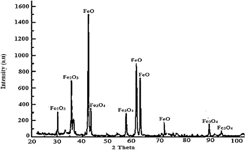
Table 2 Chemical composition of iron millscale by XRF.
Iron millscale is a generic oxide consisting of FeO, Fe2O3 and Fe3O4 in differing proportions. FeO is the largest component (69 wt.%) of the oxides in millscale, and it is the closest to the equilibrium state. This implies that FeO is the most active oxide and will invariably exert a profound influence on the physical and mechanical behaviours of the millscale. Considering the characteristic high heat conductivity of iron (80.4 W m−1 K−1), iron millscale as a component in a brake pad could be a potential heat dissipating material. This could prevent possible adiabatic heating within the brake assembly, thereby preventing heat build-up that could cause the warpage of the brake pad in operation, which is not desirable.
SiO2 () is the major compound present, while other compounds, such as alumina (Al2O3), iron (iii) oxide (Fe2O3), magnesia (MgO), and calcium oxide (CaO) are present in trace amounts. The XRD spectra () show that silica sand particles exhibit characteristics peaks at various Bragg’s angles. It is also observed that haematite (Fe2O3) and calcium oxide (CaO) peaks have broadly lower intensities compared to the silica peak. Silica sand particles exhibit characteristics peaks at various Bragg’s angles with the crystalline silica peak at 26° having the highest intensity (700 counts) followed by alumina (Al2O3) with intensity of 160 counts. As established by a previous study [Citation10], silica is the major mineralogical phase in the diffraction spectra, while the other compounds have broadly lower intensities.
Fig. 3 XRD spectra of silica sand particles.
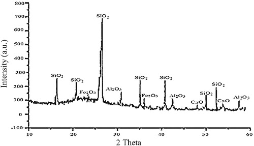
Table 3 Chemical composition of silica sand by XRF.
Silica is a chemically inert and hard material with a low density, 2.65 g/cm3, and high melting point (1610 °C). These characteristics can be attributed to the strength of the bonds between the atoms. Further, its low permeability to liquid ingression has the potential for improved dimensional stability due to its low moisture absorption behaviour coupled with the lighter weight arising from the low density. The XRF result () indicates the presence of up to 0.2% alumina in the silica. This represents a significant difference from the commonly available silica sand. The suitability of silica as a brake pad material is complemented by its availability, thereby making it cost competitive.
MgO () is the dominant compound, present at up to 98.8 wt.%. This level of purity is capable of enhancing the material’s intrinsic physical and mechanical properties. The XRD spectra () confirms magnesia (MgO) as the major mineralogical phase with the highest peak of 4500 counts at almost 27° whereas the minor phase, calcium oxide (CaO) has a peak of 500 counts at Bragg’s angles of 37° and 43°. Magnesia has a high melting temperature of 2827 ± 30 °C, specific heat capacity of 37.8 J mol−1 K−1 and has been proven to be thermally stable at elevated temperatures [Citation11]. The material also combines these characteristics with excellent abrasion and erosion resistance [Citation12]. Thus, magnesia is a potential suitable friction/thermal matrix material for applications in areas where high resistance to thermal stress and abrasive wear are required.
Fig. 4 XRD spectra of magnesia powder.
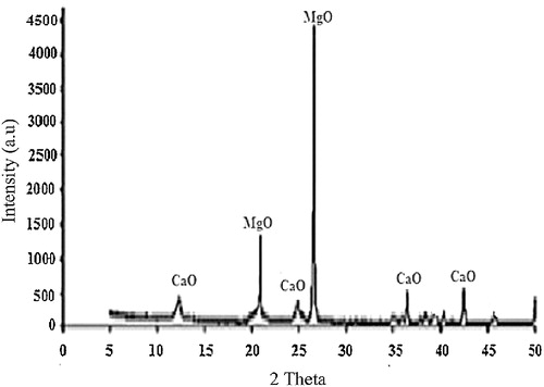
Table 4 Chemical composition of magnesia by XRF.
The chemical composition () of the as-received bentonite powder by XRF shows that SiO2 (63 wt.%) and Al2O3 (23 wt.%) are present. The XRD spectra () show that SiO2 has the highest intensity among the compounds. These results indicate that the bentonite used belongs to the alumino-silicate group. It has been established that bentonite possesses high thermal shock resistance, refractoriness, high compressive strength, resistance to abrasive wear, and low porosity, which are desirable [Citation13]. It also has the potential to confer cohesion and strength onto silica sand [Citation14].
Fig. 5 XRD spectra of the as-received bentonite clay powder.
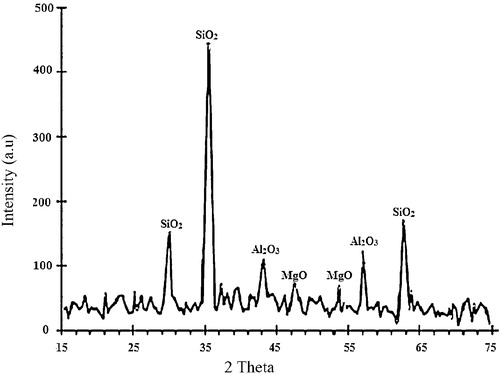
Table 5 Chemical composition of as-received bentonite powder by XRF.
3.2 Chemical reactions
Iron (II) oxide (FeO) particles react with water to form iron (II) hydroxide, which decomposes at a high sintering temperature.(4)
(4)
(5)
(5)
Magnesia (MgO) has high affinity for water. Hence, it also reacts with water to form Magnesium hydroxide, which also decomposes at a high sintering temperature.(6)
(6)
(7)
(7)
Silica reacts with bentonite in the presence of water during high temperature sintering to form a ceramic compound (mullite), which exhibits excellent high temperature properties with improved thermal shock and thermal stress resistance owing to the low thermal expansion, good strength, and high wear resistance.(8)
(8)
In all these reactions, there is the evaporation of water from the products of the reaction due to the high sintering temperature (800–1350 °C), leaving FeO, MgO, and mullite as the constituents of the samples.
3.3 Microstructure
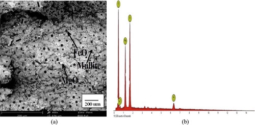
The SEM micrographs (a–a) show that the samples are made up of different additives, which confirms that they are heterogeneous with differences in the geometry of the particles, including globular and needle-like structures. The EDS spectrographs show a good combination of elemental distribution, which also reflects on the heterogeneous nature of the composites. Different sizes of particles or elements also contributed to the heterogeneous distribution. The EDS spectrographs of the composites show the presence of O, Si, Al, Mg, Fe, and Ca, but the unreinforced (control) does not contain Fe (b). There are also indistinguishable peaks in the spectrographs, indicating the presence of other elements in very small amounts. The white spots in the micrographs are particles of magnesia, while the dark spots are FeO particles from the millscale. The ash coloured needle-like region of the matrix indicates the presence of mullite (3Al2O3·2SiO2), a highly crystalline compound from bentonite clay-silica mixture (a–a) formed due to the high sintering temperature (1350 °C) used in the production of the samples. Generally, from the micrographs of the reinforced samples (a and a), the iron millscale (FeO) particles are well distributed in the matrix without any form of segregation. The interfacial bonding between the reinforcement and the matrix is enhanced by the relatively close-spacing of the FeO particles. This also suggests a good vitrification of the reinforced composites during sintering.
Fig. 6 (a) SEM; (b) EDS of the unreinforced ceramic composite (control).
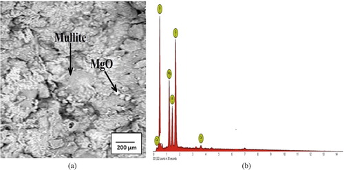
Fig. 7 (a) SEM; (b) EDS of the 10 wt.% 106 μm millscale reinforced ceramic composite.
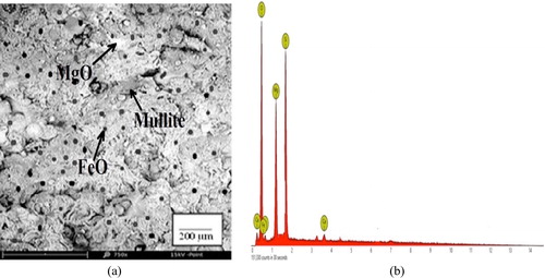
Fig. 8 (a) SEM; (b) EDS of the 25 wt.% 106 μm millscale reinforced ceramic composite.
3.4 Density
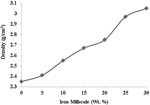
The unreinforced hybrid ceramic composite has a density of 2.35 g/cm3, while the reinforced composite at 30 wt.% has a density of 3.05 g/cm3; this represents 29.79% increase in density. There is a progressive increase in the densities of the reinforced hybrid ceramic composites with increasing weight fractions of the millscale particles (). This may be attributed to a relatively high packing factor of millscale particles, as the concentration increasing within the matrix thereby increases the density of the composites. This behaviour is further enhanced by the effective fusion of millscale particles during sintering to form a coherent body with the matrix. This suggests good vitrification of the reinforced composites during sintering. This agrees well with the fact that iron-based friction materials retain some particular properties, such as high density level [Citation15]. The density increment also seems to be due to the deposition of iron as a result of diffusion into the ceramic phase, which agrees well with the result of iron infiltration in ceramics, as reported during in situ TiC-Fe-Al2O3-TiAl/Ti3Al composite coating processing using centrifugal assisted combustion synthesis [Citation16].
Fig. 9 Effect of varied iron millscale particles addition on the density of 106 μm millscale particles.
3.5 Porosity
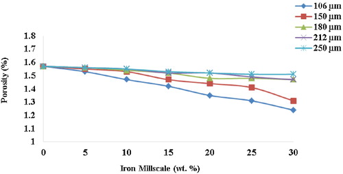
The porosity level of the unreinforced hybrid ceramic composite is 1.57%, which progressively decreased to 1.24% at 30 wt.% for the 106 μm reinforced composite (); this is a percentage decrease of 21%, which is quite significant. This compares very well with conventional or commercial brake pads. The decrease in the values of porosity with increasing weight fractions of millscale particles is due to particle agglomeration, which suggests an improved vitrification of the reinforced composites during high temperature sintering. Low porosity enhances the achievement of compact and dense composite materials with the tendency to improve the mechanical properties [Citation17]. This is also in agreement with the postulation that pores tend to shrink during sintering. This results in good bonding of the particles, which greatly reduces porosity and enhances the plasticity of ceramic composites reinforced by metal particles [Citation18].
Fig. 10 Effect of varied iron millscale particles addition on porosity of the composites.
3.6 Linear shrinkage
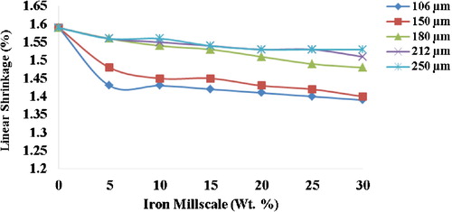
The linear shrinkage level of the unreinforced hybrid ceramic composite is 1.59%, which progressively decreased to 1.39% at 30 wt.% reinforcement for the 106 μm reinforced composite (). The percentage decrease (13%) is quite significant. This could be a result of the bonding between particles at the high sintering temperature. This agrees well with the postulation that good bonding of particles during high temperature sintering greatly enhances the linear shrinkage of composites with a reduction in inter-particles separation [Citation19].
Fig. 11 Effect of varied iron millscale particles addition on linear shrinkage of the composites.
3.7 Impact energy
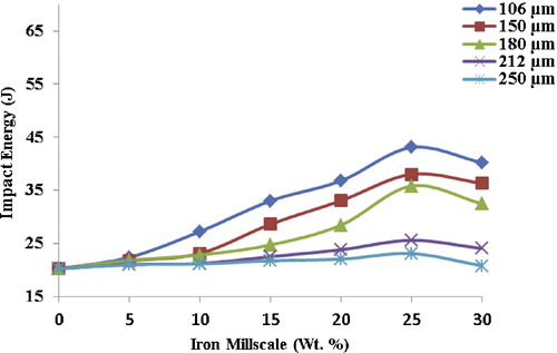
The impact energy gives an indication of the toughness of the composite, and it increases progressively with an increase in reinforcement. The maximum impact energy (43.07 J) was obtained by sample A at 25 wt.% (), representing a substantial 53% increase over the unreinforced sample. The significant increase in impact energy is strongly predicated on fine particles size, their uniform distribution within the matrix, and the strong interfacial bonding between the metallic and the ceramic phases [Citation20]. The increase in the weight fraction of FeO particles (metal phase) confers on the samples the level of plasticity sufficient to absorb energy, thereby increasing the impact energy. Invariably, increasing the weight fraction of iron millscale particles (FeO) led to an increase in elasticity within the composite core, thereby increasing its toughness [Citation21].
Fig. 12 Effect of varied iron millscale particles addition on impact energy of the composites.
3.8 Compressive strength
The compressive strength of a material is the measure of its capacity to withstand loads tending to cause lateral reduction. As evident from , there is an increase in the compressive strength of all the samples, with the 106 μm millscale reinforced sample exhibiting the maximum compressive strength (114.17 MN/m2) at 25 wt.%. This represents a 42% increase over the unreinforced. Small particles enhance the densification, which correspondingly improves the mechanical properties [Citation20]. Small particles are more effective in strengthening composites than coarse particles for the same weight fraction because smaller grain sizes increase the frequency with which dislocations encounter grain boundaries, thus requiring larger stresses for deformation to occur [Citation22]. The strong interfacial bonding between the metallic and the ceramic phases also contributed to the enhancement of the compressive strength.
Fig. 13 Effect of varied iron millscale particles addition on compressive strength of the composites.
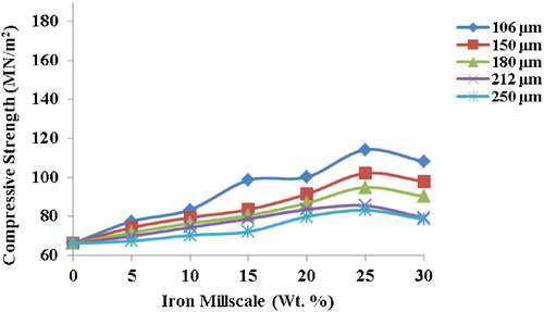
Further comparison with the results of previous studies on existing conventional or commercial brake pads () shows that the compressive strength of the composite compares very well with other brake pads. This is an indication that it will perform well in service.
Table 6 Comparison with other brake pads [Citation23,Citation24].
4 Conclusion
The development and characterisation of iron millscale particle reinforced ceramic matrix composite using varied weight percentages of reinforcement has been undertaken, with the 106 μm millscale reinforced sample exhibiting desirable physical and mechanical properties in terms of density (2.97 g/cm3), porosity (1.24%), linear shrinkage (1.39%), impact energy (43.07 J), compressive strength (114.17 MN/m2), and shear strength (63.86 MN/m2). The low density implies low weight, which will result into low fuel consumption for aircrafts and automobiles. The low porosity obtained enhances the achievement of compact and dense composite brake pad materials with the tendency to improve the mechanical properties, while relatively low linear shrinkage will ensure dimensional stability under service conditions. These values compare very well with the values of brake pads obtained in previous works and conventional/commercial brake pads (). indicating a potential for effective performance in service.
Notes
Peer review under responsibility of Taibah University
References
- S.N.NageshC.SiddarajuS.V.PrakashM.R.RameshCharacterisation of brake pads by variation in composition of friction materialsProc. Mater. Sci.52014295302
- J.AderiyeKaolin mineral material for automobile ceramic brake pad manufacturing industryInt. J. Technol. Enhanc. Emerg. Eng. Res.2320148488
- R.O.EdokpiaV.S.AigbodionO.B.ObiorahC.U.AtuanyaEvaluation of the properties of eco-friendly brake pad using egg shell particles–gum arabicResults Phys.201410.1016/j.rinp.2014.06.003
- T.K.FabemigunO.D.FagbemiO.OtitojuE.MgbachiuzorC.C.IgwePulp and paper-making potential of corn huskInt. J. AgriSci.442014209213
- A.A.AdebisiM.MalequeQ.H.ShahSurface temperature distribution in a composite brake rotorInt. J. Mech. Mater. Eng.632011356361
- P.MahaleA.BohariM.P.RaajhaEffect of Thermal Behaviour of Friction Man-made Wonder, Golden Jubilee Commemoration Lecture (Tenth in the Series)2014Foundry & Forge & Aerospace Divisions, Hindustan Aeronautics Limited, Bangalore, The Indian Institute of Metals10.4271/2014-01-2514 Bangalore Chapter, 1-70, Technical Papers
- M.NankoHigh-temperature oxidation of ceramic matrix composites dispersed with metallic particlesSci. Technol. Adv. Mater.62005129134
- J.Q.LiX.R.ZengJ.N.TangP.XiaoFabrication and thermal properties of YSZ-NiCr joint with an interlayer of YSZ-NiCr functionally graded materialsJ. Eur. Ceram. Soc.23200318471853
- B.KiebackA.NeubrandH.RiedelProcessing techniques for functionally graded materialsMater. Sci. Eng.A362200381105
- A.O.AjayiA.Y.AttaB.O.AderemiS.S.AdefilaNovel method of metakaolin de-alumination – preliminary investigationJ. Appl. Sci. Res.610201015391546
- www.rse.org/chemistryworld/2014 (accessed 09.04.16).
- M.A.AramendiaV.BorauC.JimenezJ.M.MarinasJ.R.RuizF.J.UrbanoAppl. Catal.24422003207215
- M.S.AbolarinO.A.OlugbojiI.C.UgwokeDetermination of moulding properties of locally available clays for casting operationsAU J. Technol.942006238242
- P.O.AtandaO.E.OlorunniwoK.AlongeO.O.OluwoleComparison of bentonite and cassava starch on the moulding properties of silica sandInt. J. Mater. Chem.24201213213610.5923/j.ijmc.20120204.03
- M.AsifK.ChandraP.S.MisraDevelopment of iron based brake friction materials by hot preform forging technique used for medium to heavy duty applicationsJ. Miner. Mater. Charact. Eng.1032011231244
- R.MahmoodianM.A.HassanM.HamdiR.YahyaR.G.RahbariIn-situ TiC-Fe-Al2O3-TiAl/Ti3Al composite coating processing using centrifugal assisted combustion synthesisComposites Part B: Eng.592014279284
- C.M.RuzaidiH.KamarudinJ.B.ShamsulM.M.A.AbdullahMechanical properties and wear behavior of brake pads produced from palm slagAdv. Mater.341–34220122630
- V.S.AigbodionJ.O.AgunsoyeV.KaluF.AsukeS.OlaMicrostructure and mechanical properties of ceramic compositesJ. Miner. Mater. Charact. Eng.962010527538
- C.I.NwoyeE.O.ObidiegwuN.E.NwankwoModel for computational analysis and predictive assessment of bulk density of fired bricks based on incurred shrinkageJ. Innov. Res. Eng. Sci.220117482
- M.S.RandelovicA.R.ZarubicaM.M.PurenovicNew Composite Materials in the Technology for Drinking Water Purification from Ionic and Colloidal Pollutants201210.5772/48390 (accessed 20.10.15)
- R.KaundalA.PatnaikA.SatapathySolid particle erosion of short glass fiber reinforced polyester compositeAm. J. Mater. Sci.2220122227
- H.LeeR.F.SpeyerHardness and fracture toughness of pressureless sintered boron carbide (B4C)J. Am. Ceram. Soc.855200212911293
- U.D.IdrisV.S.AigbodionI.J.AbubakarC.I.NwoyeEco-friendly asbestos free brake-pad: using banana peelsJ. King Saud Univ. Eng. Sci.2722015185192
- N.A.AdemohA.I.OlabisiDevelopment and evaluation of maize husks (asbestos-free) based brake padInd. Eng. Lett.5220156780