
Abstract
Landmines represent a serious environmental problem for several countries as it causes severe injured and many victims. In this paper, the response of GPR from different parameters of the landmine targets has been shown and the data is correlated with observed field experiment made in 2012 at Miami Crandon Park test site. The ability of GPR for detecting non-metallic mines with different orientations was revealed and soil effect upon the GPR signal was examined putting into consideration the soil parameters in different locations in Egypt such as in Sinai and El Alamein. The simulation results showed that PMN-2 landmine was detected at 5 cm and 15 cm depths, even at the minimum radar cross section vertical orientation. The B-Scan (2D GPR profiles) of PMN-2 target at 15 cm depth figured out high reflectivity for Wadi deposits due to large contrast between PMN-2 landmine material and soil of sand dunes.
1 Introduction
Egypt suffers from more than 20% of the total number of landmines in the world. A huge area is affected and estimated by 25,000 sq kilometres. Most of the mines and UXO are covered by thick deposits either of mud or sand. Thus the conventional detection techniques are often done with high challenges and little value. The locations of landmines can be altered in soil over time, due to weather conditions. In addition, soil type can also pose a challenge to landmine detection and clearance. In sandy soil environment of Egypt, wind moves sand sheets dramatically. Moreover, excavating and sifting of soil for mine-size objects are more difficult in case of the mine consists of plastic materials or is buried in clayey soil. In addition, some soils have high mineral content which are shadowing detectability of landmines.
Fig. 9 B-scan representation in the case of 60 degree orientation at (a) 5 cm depth and (b) 15 cm depth.
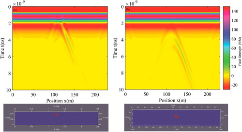
Fig. 10 B-scan representation in the case of 90 degree orientation at (a) 5 cm depth and (b) 15 cm depth.
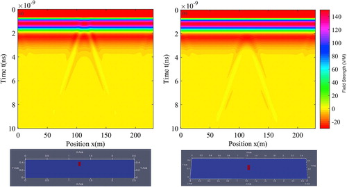
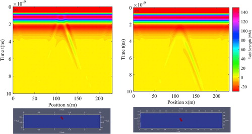
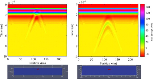
Fig. 11 B-scan representation in the case of 250 degree orientation at (a) 5 cm depth and (b) 15 cm depth.
Basic demining process requires physical prodding of earth to locate mine and its subsequent removal which is risky. The risk is sought to be minimized by introducing electromagnetic (EM) imaging equipment which generates backscatter data of the suspected region and concurrently processes it to detect presence of landmine. Ground Penetrating Radar (GPR) is considered as one of the effective geophysical technique which uses high frequency electromagnetic wave (106–109 Hz) to detect the electrical distribution for investigating the shallow subsurface medium (CitationAnnan, 1973). Steel and other metallic materials (low impedance) or PVC and other dielectric (high impedance) are common detecting target with GPR system. Detecting and removing of landmines is a complicated process due to many reasons such as the variety of landmines materials, soil types and conditions and presence of vegetation cover on ground surface in some cases.
A parametric study is carried out by CitationTang (2007) to investigate the quality of reconstructed images using ground penetrating radar due to; (a) centre frequency of the GPR excitation pulse, (b) height of transmitting and receiving antennas above ground level, and (c) proximity of buried object. An integrated software package was used to streamline computer simulation based on synthetic data generated by gprMax (CitationWarren et al., 2016). A comprehensive analysis of scattered signals from buried landmine-like targets via accurate numerical modelling of GPR responses considering various antenna-soil-target scenarios. Different characteristics in time and frequency domain are extracted and interpreted for each configuration is given in (CitationGiovannaschi et al., 2013). Time-propagation mixing modelling and forward-modelling techniques were performed and showed good correlation between modeled and measured dielectric constants of some selected soils (sandstone and limestone) in (CitationTang, 2007). The effects of vegetation, water puddles, rough surface, and complex soils were examined at (CitationGiannakis et al., 2016) and cases shown for which GPR—using the specific modeled antennas—has difficulties in clearly and easily detecting the simulated AP landmines. Additional models were constructed to investigate role of the lithology and fluid saturation on dielectric constant and GPR response (CitationMartinez and Byrnes, 2001). Magnitude of target response which affected by soil parameters is an important factor in assessing the quality of the detection and signature extraction. Variation of these magnitudes with regards to the parameters are susceptible to modify them through parametric study of such responses was seen in (CitationVan Den Bosch et al., 2006). Targets and soil characteristics are affecting on the back-scattered radar signal. To evaluate these changes in a quantitative way a similarity measure was performed (via the correlation coefficient) between time domain signatures (CitationGonzalez-Huici, 2012). Physical and geometrical parameters that influence target radar response are shown below (Citationvan den Bosch, 2006);
| • | Soil EM constitutive parameters µr, εr. | ||||
| • | Target depth and orientation with respect to the soil surface. | ||||
Low and non-metallic landmines at different depths (25, 30, 35, and 40 cm) are detected by using GPR with three different antenna frequencies (400, 900 and, 1500 MHz) as previously discussed by CitationMetwaly (2007). The research exanimates in detail the effect of weathering conditions that have to be taken into consideration by simulating the surrounding burial environments. Moreover, the work studies the effect of these weathering conditions on plastic landmines that result in rotating them.
Landmines orientations and electromagnetic (EM) characteristics of soil are the most important factors that control the radar response. Landmine physical properties also play a vital role, because its EM properties which are comparable to the EM soil parameters, shape, depth and orientations.
In this work, field measurements of landmines detection using GPR which were performed at Miami Crandon Park test site were discussed. As well as effect of changing landmines orientation and soil parameters which are suitable with Egyptian soil were simulated.
2 Materials and methods
2.1 Detecting and locating PMN-2 and type-72 (experimental data)
A 3D GPR experiment was conducted to visualize small buried low-metal landmines. This experiment was carried out at Miami Crandon Park, South Florida in USA. The soil of this site is sandy soil with very low moisture content. Plastic landmine models (PMN-2 and Type 72) were buried in 8 m × 10 m area at different depths (0, 5, 10, and 15 cm) as well as in two different positions, namely horizontal and 45° inclination ().
Table 1 Set-up configurations of landmine models detection experiment.
A 500 MHz commercial GPR system (Mala Geoscience, RAMAC GPR) was setup with laser positioning system and used for this measurement to scan the test site with 2.5 cm inline spacing. Two 3D GPR measurements were carried out in this site (CitationSato et al., 2010).
2.2 Targets model
The PMN-2 mine casing is made from injection-molded plastic. The top of the mine has a black rubber X-shaped pressure plate. Also, the Type 72 anti-personnel blast mine is a small plastic mine made in China as shown in . shows the specifications of the previous targets. shows the B-Scan (2D) GPR image of the buried landmine models at 5 cm depth at previous test site.
Fig. 1 The buried PMN-2 and type 72 mines.
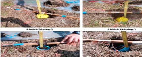
Fig. 2 B-Scan (2D) GPR image of the buried landmine models at 5 cm depth.
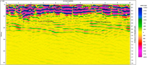
Table 2 Landmines (PMN-2 and type 72) specifications.
2.3 Simulation of PMN-2 and TYPE-72 landmines
In order to investigate the behaviour of the landmine models at different orientation, GPR simulations were performed using gprMAX. shows the simulation parameters for different landmines models (PMN-2 and Type 72). shows simulation image of GPR of one lain which contain four targets two types of each of them were buried at depth 5 and as well as in two different positions, namely horizontal and 45° inclination. The observed data of simulation showed the consistency with measured data. Thus the simulation results revelled.
Fig. 3 Simulation image of the buried landmine models at 5 cm depth.
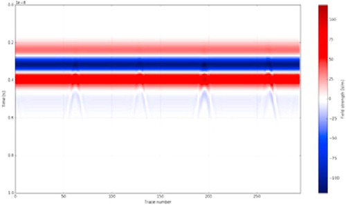
Table 3 Simulation parameters of plane wave models.
3 Results and discussion
3.1 PMN-2 models representation with different inclinations and depths
In this paper, the reflection of GPR signals with a varying tilting angle θ between soil surface and the top of target surface were carried out by using gprMAX program. Angles were varied as (0° 30°, 60°, 90°, 260°, and 340°) at two different depths (5cm, and 15 cm) as shown in using dielectric permittivity ε = 4. The size of Type 72 landmine is smaller than PMN-2 so that, it was not appropriate for check in the reflection behaviour for different orientation (see ).
Fig. 4 Different positions of PMN-2 at two depths 5 cm and 15 cm.
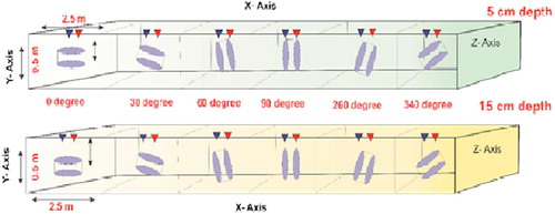
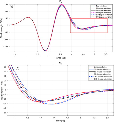
Fig. 5 A-scan representation for all orientations at 5 cm depth. (b) A-scan is focused on the change in the crest and trough.
3.2 A-scans representation of all inclinations in the case of 5 cm depth
This part shows the reflection of PMN-2 landmine at depth 5 cm and at different orientation angles were examined for the same used model parameters in . These figures are the results of multiple modelling at varied angles which collecting by Matlab program.
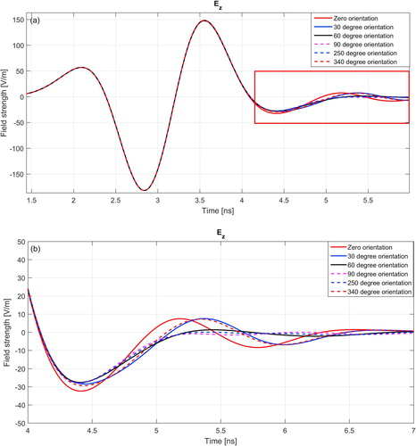
3.3 A-scans representation of all inclination in the case of 15 cm depth
The tilting angle θ of target (PMN-2) was varied at depth 15 cm as formerly; the reflection of target at this depth can be clearly discriminated from ground reflection. The A-scan representation for all inclinations at 15 cm is shown in . At (b) there are deviations between the different reflections of target which occurred as the result of varying the orientation of target. The minimum reflection was caused at tilting angle 90° (vertical position) where at this position the radar cross section of the target is the smallest. Furthermore the starting position of reflected signal was different due to the effect of shifting the initial point of target where the radar signal reflected at the various angles.
Fig. 6 A-scan representation for all orientations at 15 cm depth. (b) A-scan is focused on the change in the crest and trough.
3.4 B-scan representation in the case of zero degree inclination at 5 and 15 cm depths
B-scan of the zero tilting angle θ (horizontal position) of target (PMN-2) at depths 5 and 15 cm are determined as shown in . The reflection of target at depth 15 cm was more clearly than the reflection of target at 5 cm depth according to the minimum vertical resolution which was calculated by (CitationAnnan, 2003). – show B-scans of PMN-2 landmine with different inclination angles (30°, 60°, 90°, 26°, and 340°) at two different depths 5 and 15 cm. As shown in – the maximum reflection was arisen at horizontal orientation (θ = 0°) at depth 15 cm where the radar cross section are the highest.
Fig. 7 B-scan representation in the case of zero degree orientation at (a) 5 cm depth and (b) 15 cm depth.
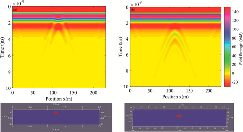
Fig. 8 B-scan representation in the case of 30 degree orientation at (a) 5 cm depth and (b) 15 cm depth.
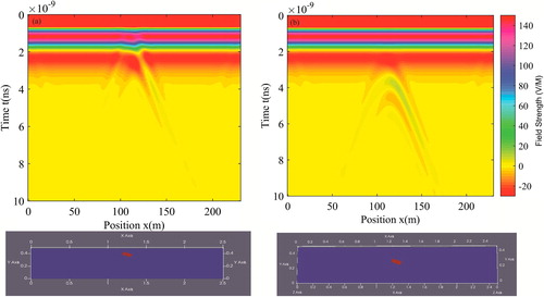
Fig. 12 B-scan representation in the case of 340 degree orientation at (a) 5 cm depth and (b) 15 cm depth.
3.5 PMN-2 models representation with different soil parameters
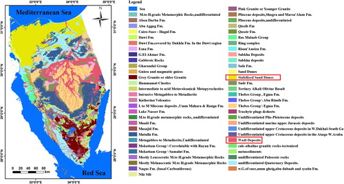
Dielectric constant is a critical parameter for GPR detections because it controls the propagation velocity of the electromagnetic waves through the material, the reflection coefficients across interfaces of different materials, and the vertical and horizontal imaging resolution. Furthermore the changing in soil parameters (permittivity ε & conductivity σ) is studied, according to the nature of the soil found in Sinai, Egypt. The areas to the east, including the Sinai Peninsula were contaminated between 1956 and 1973 due to hostilities between Egypt and Israel. This area is polluted with plastic landmines and has contained two types of soils which have different parameters. The first one identified as Wadi deposits (coastal sandstone, limestone and clay) where its parameters are; dielectric permittivity (ε) = 10 and conductivity (σ) = 0. While the parameters of sand dunes are; dielectric permittivity (ε) = 4–6 and conductivity (σ) = 10−6 as shown in Sinai geological map ().
Fig. 13 Sinai geological map.
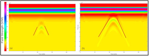
shows b-scan of two different soil parameters at horizontal position of target (PMN-2) at depth 15 cm. The model of target is buried in Wadi deposit presented in (a), another one is buried in sand dunes as exposed in (b). There are variations in target reflection as a consequence of different soil parameters but still the target under this condition can be recognized.
Fig. 14 B-scan representation in the case of different soil parameters (a) Wadi deposit and (b) Sand dunes.
4 Conclusion
In this paper, the simulation showed almost the same results obtained in the real field experiment. This means that the simulation work is reliable and can be used in configuring the landmines positions at other locations. The PMN-2 landmine was successfully detected by the GPR at depths of 5 and 15 cm even at the minimum radar cross section of vertical orientation.
The B-scan image and the reflection of PMN-2 at depth of 15 cm which has mean obtained in sand dunes soil were much clearer than that obtained at the Wadi deposits site. This is because of the higher contrast between the PMN-2 and soil parameters (electrical properties) of sand dunes site.
Acknowledgment
The authors would like to thank the Sato Lab, Centre for Northeast Asian Studies, Tohoku University, Japan for providing the experimental materials of the GPR work that has been done in collaboration with Miami University in USA. The authors like to express their thanks to Prof. Dr. Hamed Nofal and Prof. Dr. Mahmoud Mohana for reviewing the manuscript. Also, thanks our colleague Samah Elbarbary that helped us in mapping.
Notes
Peer review under responsibility of National Research Institute of Astronomy and Geophysics.
References
- Martinez, Alex, Byrnes, Alan P., 2001. Modelling dielectric-constant values of geologic materials: an aid to ground-penetrating radar data collection and interpretation. Curr. Res. Earth Sci., Bul. 247, part 1. <http://www.kgs.ukans.edu/Current/2001/martinez/martinez1.hmtl>.
- A.P.AnnanRadio interferometry depth sounding: Part 1. Theoretical discussionGeophysics3831973557580
- Annan, A.P., 2003. Ground Penetrating Radar: Principles, Procedures & Applications. Sensors & Software Inc, Mississauga.
- Giovannaschi, Fabio, Gonzalez-Huici, M.A., Uschkerat, Udo, 2013. A parametric analysis of time and frequency domain GPR scattering signatures from buried landmine-like targets. In: Proceedings of SPIE – The International Society for Optical Engineering.
- I.GiannakisA.GiannopoulosC.WarrenA realistic FDTD numerical modeling framework of ground penetrating radar for landmine detectionIEEE J. Sel. Top. Appl. Earth Observations Rem. Sens.912016115
- Gonzalez-Huici, M.A., 2012. A strategy for landmine detection and recognition using simulated GPR responses. In: Proceedings 14th Conference on Ground Penetrating Radar, Shanghai.
- van den Bosch, Idesblad, 2006. Accurate modelling of ground penetrating radar for detection and signature extracting of mine-like targets buried in stratified media. PhD thesis, University Catholique de Louvain and Royal Military Academy, Belgium.
- M.MetwalyDetection of metallic and plastic landmines using the GPR and 2-D resistivity techniquesNat. Hazards Earth Syst. Sci.72007755763
- Sato, Motoyuki, Gaber, Ahmed, Yokota, Yuya, Grasmueck, Mark, Marchesini, Pierpaolo, 2010. CCD camera and IGPS tracking of geophysical sensors for visualization of buried explosive devices. International Conference on Indoor Positioning and Indoor Navigation (IPIN), Zürich, Switzerland, pp. 15–17.
- TeeTangA parametric study of imaging subsurface objects using ground penetrating radarJ. Jpn. Soc. Appl. Electrom. Mech.152007
- I.Van Den BoschS.LambotI.HynenM.AcheroyB.DuyrtsAccurate and efficient modelling of monostatic GPR signal of dielectric targets buried in satisfied mediaJ. Electrom. Waves Appl.32006283290
- C.WarrenA.GiannopoulosI.GiannakisgprMax: Open source software to simulate electromagnetic wave propagation for Ground Penetrating RadarComput. Phys. Commun.2092016163170