
 ?Mathematical formulae have been encoded as MathML and are displayed in this HTML version using MathJax in order to improve their display. Uncheck the box to turn MathJax off. This feature requires Javascript. Click on a formula to zoom.
Abstract
This research aims to study the hot water recirculation at the power plants intakes due to the discharge from the plant cooling system into a low flow receiving water body. To achieve this objective, a 3Dnumerical model was employed to study the effect of the main parameters in this phenomena such as the plant intake length (L), the distance between the plant intake and outfall (S), the water depth under the intake skimmer wall (h) and the water depth just upstream the intake (D) on the recirculation of hot water to the plant intake. Eight scenarios were tested and two mathematical formulas accounting for the effect of these parameters on the hot water concentration at the plant intake were deduced. Physical model tests were carried out to verify the accuracy of the two deduced formulas. The study results indicated that the measured thermal concentrations in the physical model tests coincide with those calculated by the two above-mentioned mathematical formulas.
1 Introduction
The greatest single source of man-made heat addition to the world's rivers, lakes and oceans comes from electricity generating plants which have large cooling requirements. Widespread influence of thermal water depends on several factors such as the volume and temperature of hot water, receiving water body temperature (near outfall), flow or mass circulation of water around the outfall (CitationPitchaikani et al., 2010). Heat transfer mechanisms occurring in receiving water bodies are part of the physical properties that may be affected by tides, waves, river discharge, salinity, water depth, bathymetry, heat sources, and hydraulic structures in the water body (CitationHuboyo and Zaman, 2007).
The possibility of recirculation of hot water into cooling water intakes is of particularly concern to hydraulic engineers in building thermal power stations because of its adverse impacts on the plant efficiency and operation. Thermal recirculation occurs when the thermal water of the outfall discharged water causes an increase of water temperature at the intake, which in turn will provide a further temperature increase at the outfall and a continuous temperature rise at the intake and outfall. By this, the efficiency of the cooling system reduces with time which will ultimately reduce the power plant efficiency. There are basically two types of intakes generally grouped as onshore and offshore intakes. It is desirable for the intake to be well low the water surface (maximum 0.8 of water depth to avoid the entry of sediment into the intake structure). For economic considerations, it is obviously desirable that the intake should be as close to the shore as possible (CitationJirka, 1979). This research focuses on the transport and advection phenomena of the plume, in particular the recirculation of effluents to the plant intake in water bodies with low velocity currents (current velocity is less than 0.1 m/s).
2 Purpose of the study and methodology
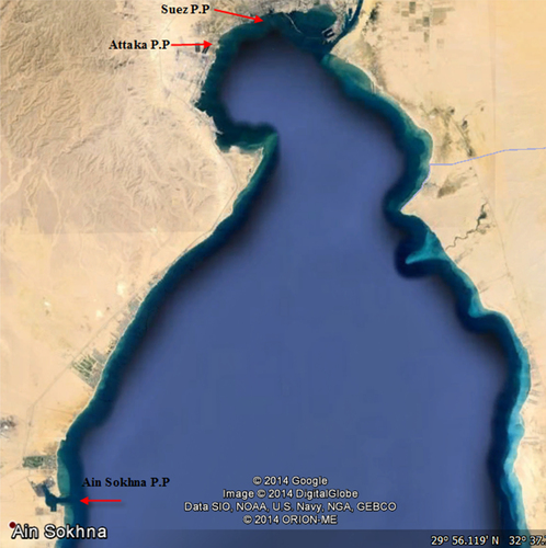
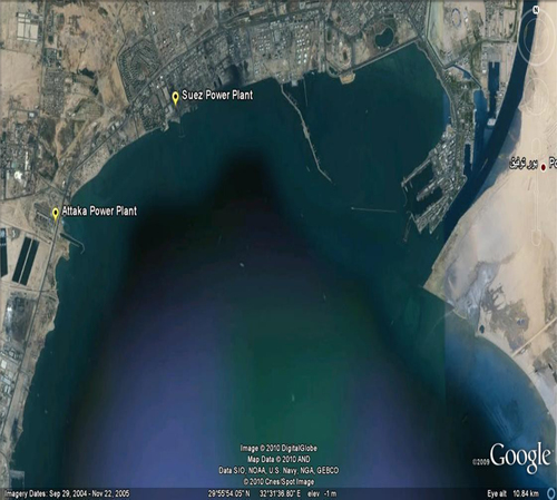
The main purpose of this study is to investigate the effect of the thermal power plant intake and water body parameters on the hot water recirculation at the plant intake. It well focuses on the effect of the following parameters: the plant intake length measured from the shore line (L), the distance between the plant intake and outfall (S), the water depth under the intake skimmer wall (h) and the water depth just upstream of the intake (D). The two parameters L and S are representing the surface area confined between the intake and outfall. So, they were taken as one term (L/S). Also, the two parameters h and D are representing the available height for the intake to abstract water from the ambient with respect to the whole water ambient depth. So, they were taken as one-dimensional less term (h/D). For this purpose, a hydro-thermal 3D numerical model was employed to investigate the effect of the above-mentioned parameters on the hot water recirculation to the plant intake. The model was well calibrated with field measurements representing the average Suez Gulf characteristics at the location of three power plants that use its water for its cooling system (Old and New Suez Power Plant, Attaka Power Plant and El-Ain El-Sokhna Power Plant) (CitationHRI Report 159, 2010). Other parameters as the ambient current and wave direction affect the hot water recirculation at the plant intake. According to the Egyptian reference wind charts and Atlas wind maps, the maximum wind forces affecting the Suez Gulf district are in the winter season and are recognized by prevailing wind directions of (North and North West). As observed, the maximum wind intensities at the proposed project are coming from the directions (North-North West) to (West-North West), which have a very slight effect on wave propagation at the area as these wind forces are more or less blowing from land direction. On the other hand, almost small wind is blowing from the sea side, which is also exposed to very narrow and limited water fetch. Subsequently, it was decided to carry out all tests in this study under calm wind and low ambient current condition. shows the overall view of the Suez Gulf Power Plants and shows the Suez Gulf study area. For model development and calibration, reference is made to CitationHRI Report 160 (2010). The three-dimensional (3D) hydrothermal numerical model was used in which different scenarios were tested to account for the effect of the intake parameters in the study area. Also, physical model for the Suez Gulf and New Suez Power Plant was used as a case study and the transport and advection of the plume was simulated to confirm the final results of the numerical model.
3 Numerical model setup
The pollutant transport task comprises the calibration and application of a dimensional model of the study area to reproduce the distribution of the flow. The relevant discharge plume can be simulated and recirculation of excess temperature is deduced (CitationDhanus et al., 2012).
The numerical model (Delft3D Software Package of Delft Hydraulics – The Netherlands) was used in this study. The model describes the behavior of the plume, the subsequent mixing processes and area of impact and capable of reproducing the most important processes that affect the dissipation and dilution of excess heat introduced by the plant to the receiving water body. The simulation of intake/outfall configuration was done in the model by increasing the resolution of the model grid through refining the grid cells at the vicinity of the plant. Two domains with different grid resolutions were generated. A detailed model with fine grid resolution was produced at the plant vicinity including the intake/outfall configuration of the plant. The detailed model simulates enough area of the long shore and off shore direction. The grid size of the detailed model is 10 m × 10 m. A courser grid resolution with grid size of 30 m × 30 m was carried out to cover the remaining study area which is named as the “overall model”. The Domain Decomposition technique, D.D. was used to make online coupling between the two domains, detailed and overall models. D.D. is a technique, in which a model is divided into several smaller model domains (CitationVollebregt, 1997). The subdivision is based on the horizontal and vertical model resolution required for adequately simulating physical processes. Then, the computations can be performed separately on these domains. The communication between the domains takes place along internal boundaries, or so-called DD-boundaries. The solution process in this numerical method can be easily accelerated by adding a domain decomposition technique (CitationRoest, 1997). The use of the D.D. approach is especially useful in the present application, since we have to deal with some structures which have a significant influence on the transport and diffusion-reaction of the effluent hot water (CitationSommeijer and Kok, 1997). The computational time step was taken as 0.10 min to produce adequately stable results. All simulations were tested for a period of time of 20 days which include one-week spin up and one spring-neap tidal cycle in the Suez Gulf which presents the most seasonal variation during the year.
4 Numerical model scenarios
To study the effect of the plant intake length (L), the distance between the plant intake and outfall (S), the water depth under the intake skimmer wall (h) and the water depth just upstream of the intake (D) on the hot water recirculation to the power plant intake, a detailed hydrothermal numerical flow model as mentioned above was employed. shows a detailed view for the above-mentioned parameters. The resolution of the model grid in the horizontal direction was increased considerably to be able to simulate the intake basin and the skimmer wall very accurately. The modeled and observed water levels are compared at stations TG1 (Suez Station) and TG2 (Attica Station) as shown in . and present the results in spring-neap tidal cycles which present the most seasonal variation along the year. From these figures it is observed that the modeled and observed water levels match well which means that the model is well calibrated. Eight model scenarios were tested including different values of the above-mentioned parameters. The model scenarios were conducted for the critical case of calm wind at which the stagnant plume from the plants is prevailed as this condition is considered as the critical case which produces the maximum excess temperature above the ambient water. Employing the adapted model, each scenario was run for a 20 days period which includes one week for model spin up and two weeks of spring-neap tidal cycle representing the most seasonal tidal variation during the year in Suez Gulf at the location of Suez, Attaka and El-Ain El-Sokhna Power Plants. At each scenario, the increased water temperature at the intake vicinity (directly upstream of the skimmer wall) and inside the intake (directly downstream of the skimmer wall) was measured to study the effect of the surface area confined between the intake and outfall (L × S) and the dimensionless parameter (h/D) on the hot water recirculation to the intake. and present an overview of the model scenarios simulations with varied L × S and h/D subsequently.
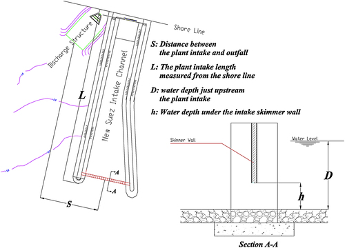
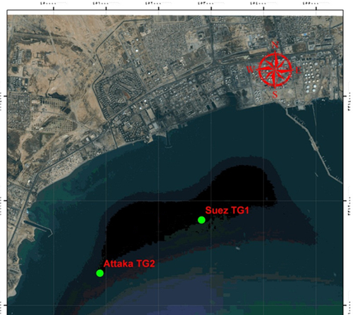
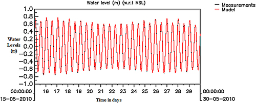
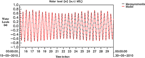
Table 1 Model scenarios simulations with varied L × S values.
Table 2 Model scenarios simulations with varied h/D ratios.
5 Data analysis
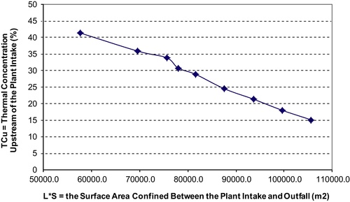
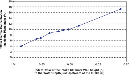
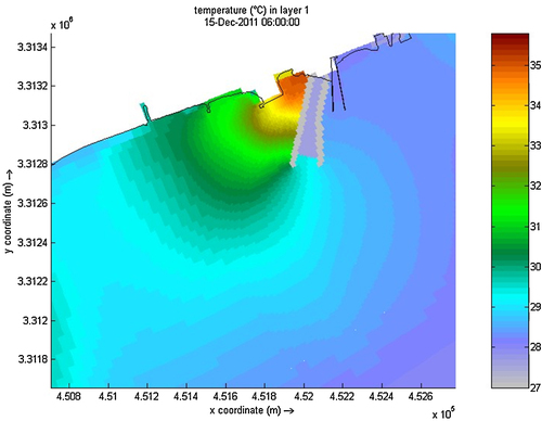
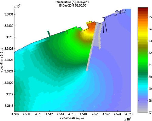
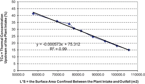
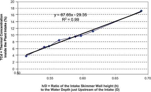
and indicate the thermal concentration at the ambient water upstream and inside the plant intake, respectively for all scenarios. The figures show that, the thermal concentration at the ambient increases with the decrease of L/S value and the increase of h/D value. and give an example of the temperature distribution near the water surface at the plant vicinity for scenarios 1 and 8 respectively. In case of scenario 1, for which L × S = 57,600 and h/D = 0.69, the thermal concentration result in a value of 41.3% just upstream of the plant intake and 17.5% downstream of the skimmer wall (i.e. inside the plant intake). In case of scenario 8, the above ratios decreased more and reached to 15% just upstream of the plant intake and 5% inside it due to the increase of L × S value to 105,600 and the h/D value to 0.51 instead of 57,600 and 0.69 respectively in scenario 1. The improvement of thermal concentration ratios due to increasing L × S and h/D values is referred to the ability of these parameters to improve the mixing process upstream of the plant intake and confine the hot water near to the water surface. Water temperature stratification along the water columns was very limited when using high skimmer wall and long intake which gives the plant intake the ability to abstract water with low thermal concentration (CitationMiller and Brighouse, 1984).
Utilizing the results of all tested scenarios, two mathematical formulas indicating the relation between the affecting parameters mentioned earlier and the hot water concentration at the plant intake were deduced (as mentioned in item No. 2, the ambient current velocity and wave direction was kept constant in this study). and show the relation between TC and L × S as well as h/D, respectively. The two formulas are as follows:(1)
(1)
(2)
(2) where TC, thermal concentration: the ratio between the difference of water temperature at distance L (Tl) and the natural ambient temperature (Ta) to the difference of outfall temperature (To) and the natural ambient temperature (Ta)
TCu, thermal concentration at the plant intake vicinity (just upstream of the skimmer wall); TCd, thermal concentration inside the plant intake (just downstream of the skimmer wall)Ta, local ambient temperature without thermal effluent; Tl, ambient temperature at any point with thermal effluent; To, effluent temperature.
6 New Suez Power Plant hydrothermal physical model
In order to verify the numerical model results and check the validity and accuracy of the two deduced equations (Equation(1)(1)
(1) Equation(2)
(2)
(2) ), a distorted physical model with horizontal scale 1:100 and vertical scale 1:20 for the New Suez Power Plant (NSPP) was used as a case study. The NSPP physical model was constructed at HRI experimental hall. The model represents a length of 5800 m parallel to the shoreline of the Suez Gulf and 1800 m normal to it. The model scales were determined according to the similarity laws and the available space. The model scales in the horizontal and vertical directions are 1:100 and 1:20 respectively (CitationHRI Report 126, 2012). A series of Suez Plant intakes with different lengths and skimmer wall heights were tested in the NSPP physical model and the values of h/D and L × S were computed. Also, the water depth at the skimmer wall location (D) was measured in all tests. The tests’ results showed that there was a recirculation of the effluents to the proposed intakes. and indicate the measured excess temperature above the ambient water temperature for all tests at the locations upstream of the plant intake and inside it, respectively. Applying the two deduced equations with the computed values of h/D and L × S related to the tested plant intakes, the excess water temperature upstream of the plant intake and inside it were deduced. As an example, and show the contour lines of the excess temperature above the ambient water in the study area and the temperature distribution around the New Suez Power Plant in case of L × S = 57,600 and h/D = 0.69. The measured excess temperature upstream and inside the plant intake in this test was 3.25 and 1.4 °C, while the corresponding two values of excess temperature computed by using the two deduced formulas were 3.5 and 1.6 °C, which means that the difference between the measured and deduced excess temperature did not exceed 0.25 °C. and show the relation between the measured and deduced thermal concentration just upstream and downstream of the skimmer wall of the plant intake for all tests. The measured response values compared with the predicted values showed that most of the values plotted are in range of confidence interval of 90%. Therefore the agreement between the measured and predicted results is satisfactory. This indicates the employability of these formulas for predicting the concentration of the returnable hot water to the plants intakes in low flow water bodies.


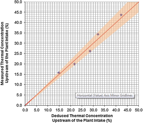
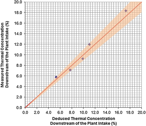
Table 3 Measured thermal concentration upstream of the NSPP intake.
Table 4 Measured thermal concentration downstream of the NSPP intake.
7 Conclusions
The study results proved that the hot water recirculation to the plant intake decreases with the increase of the power plant intake length (L), the distance between the plant intake and the outfall (S), and the water depth just upstream of the intake (D) and increase with the decrease of the water depth under the skimmer wall installed at the intake entrance (h). Utilizing these results of the numerical model scenarios, two mathematical formulas indicating the relation between the above-mentioned parameters and the hot water concentration at the plant intake were deduced. The validity and accuracy of the two deduced equations were verified by using a physical model study related to the New Suez Power Plant. A series of Suez Plant intakes with different lengths and skimmer wall heights were tested in the model. Applying the two deduced equations with using the values of h/D and L × S related to the tested plant intakes, the excess water temperature just upstream of the plant intake and inside it (just downstream the skimmer wall) were deduced. Good agreement between the measured and deduced excess water temperature at the plant intake was indicated as the maximum difference did not exceed 0.25 °C. This indicates the employability of these formulas for predicting the concentration of the returnable hot water to the plants intakes in water bodies with low velocity currents.
8 Recommendation
Based on the numerical and physical model results, it is recommended to use the deduced equations from this study for determining the hot water concentration at the power plant intakes. These equations are applied for the case of ambient low velocity currents conditions. It is recommended to use higher current velocities to establish the relation between the aforementioned parameters and the hot water recirculation. It is also recommended to carry out more intensive experimental studies to investigate the effect of other parameters like the horizontal angle of the plant outfall with the shore line and the distance between two adjacent power plants on the hot water recirculation to the plants intakes. It is also important to study the effect of the density difference between the ambient and effluent (Δρ), on the hot water recirculation to the plants intakes as it was kept constant in all scenarios tested in this study. The use of physical model is a very helpful tool for confirming and adjusting the numerical model results to insure safe application of the study outputs in the prototype.
Conflict of interest
None declared.
Notes
Peer review under responsibility of National Water Research Center.

References
- S.DhanusA.VellyN.SaptoK.WidjoCooling water recirculation modeling of Cilacap Power PlantThe Second International Conference on Port, Coastal, and Offshore Engineering (2nd ICPCO)Bandung, November 12–132012
- Hydraulics Research Institute, HRI, Report No. 159Hydrographic Survey at Suez Gulf Power Plant2010Hydraulics Research InstituteCairo, Egypt
- Hydraulics Research Institute, HRI, Report No. 160Hydro-thermal Numerical Modeling Study – Suez Power Plant2010Hydraulics Research InstituteCairo, Egypt
- Hydraulics Research Institute, HRI, Report No. 126Hydro-thermal Physical Modeling Study – Suez Power Plant2012Hydraulics Research InstituteCairo, Egypt
- H.S.HuboyoB.ZamanAnalysis of distribution of temperature and salinity wastewater combined cycle power plant-based spatial mapping system (case study: power plant-combined cycle Pond Lorok Semarang)Precip. J.3220074045
- G.H.JirkaSupercritical withdrawal from two-layered fluid systems. Part 1: two-dimensional skimmer wallJ. Hydraul. Res.1711979
- D.S.MillerB.A.BrighouseThermal Discharge: A Guide to Power and Process Plant Cooling Water Discharge into River, Lakes and Seas1984BookUnited Kingdom
- J.S.PitchaikaniG.AnanthanM.SudhakarStudies on the effect of coolant water effluent of Tuticorin thermal power station on hydro biological characteristics of Tuticorin Coastal Waters, South East Coast of IndiaCurr. Res. J. Biol. Sci.222010118123
- M.R.T.RoestPartitioning for Parallel Finite Difference Computations in Coastal Water Simulation (Ph.D. thesis)1997Delft University of TechnologyThe Netherlands
- B.P.SommeijerJ.KokDomain decomposition for an implicit shallow water transport solverInternational Conference and Exhibition, vol. 1225Vienna, Austria, April 28–301997379388
- E.A.H.VollebregtParallel Software Development Techniques for Shallow Water Models (Ph.D. thesis)1997Delft University