Abstract
Background Migration of wear debris to the periprosthetic bone is a major cause of osteolysis and implant failure. Both closed-pore porous coatings and hydroxyapatite (HA) coatings have been claimed to prevent the migration of wear debris. We investigated whether HA could augment the sealing effect of a porous coating under both stable and unstable conditions.
Methods We inserted porous-surfaced knee implants, with and without HA coating, in 16 dogs, according to a paired, randomized study design. 8 dogs had 2 implants inserted into each knee using a stable implant device and 8 dogs received 1 implant in each knee using a micro-motion (500 μm) implant device. Implants had a periimplant gap of 0.75 mm. We then injected polyethylene (PE) particles or a control solution into the knee joints on a weekly basis.
Results After 16 weeks, the rating of particles around stable implants was reduced by the HA coating from a median value of 2 (1–4) to 1 (0–1) (p = 0.01) and during micromotion from 3 (2–4) to 1 (0–3) (p = 0.002). HA-coated implants had superior bone ongrowth during stable and unstable conditions. We found no difference in bone ongrowth between PE-exposed and vehicle-exposed implants.
Interpretation Compared to a pure plasma-sprayed porous coating, a layer of HA coating provides better bone ongrowth and protects the bone-implant interface against the migration of wear debris under both stable and unstable conditions.
It is believed that wear debris in the periprosthetic tissue of hip implants contributes to bone loss and implant failure. Reduction of the effective joint space (Schmalzried et al. Citation1992) by sealing off the bone-implant interface is therefore important to reduce the migration of wear debris to the periprosthetic tissue. Non-cemented implants with smooth or grit-blasted surface have failed to protect the interface against the migration of wear debris (Bobyn et al. Citation1995, Rahbek et al. Citation2000, Citation2001). In contrast, porous-surfaced implants have a substantial sealing effect (Bobyn et al. Citation1995, Urban et al. Citation1996). Emerson et al. (Citation1999) compared partially porous-coated with circumferentially porous-coated femoral components. They observed signs of osteolysis in 40% of the cases with incomplete coating, and with circumferential coating in only 10% of the cases despite equal wear rate. The presence of distal osteolysis only in the group with partial coating indicated that wear debris had migrated along the smooth surfaces between the pads.
We have previously shown that hydroxyapatite (HA) has a sealing effect after 8 and 52 weeks (as compared to a grit-blasted surface) in a loaded stable implant model (Rahbek et al. Citation2000, Citation2001). However, whether or not HA can augment the sealing effect of a porous-coated surface is unknown. We thus compared the sealing effect of a porous surface with the sealing effect of an HA-coated porous surface. As cementless hip components are initially subjected to micromotions in the 100–500 μm range (Burke et al. Citation1991, Vanderby et al. Citation1992), which influences the fluid dynamics at the bone-implant interface and therefore the pumping of wear debris into the interface (Anthony et al. Citation1990), we included micromotion in the experimental setup.
Our hypothesis was that HA can augment the sealing effect of a porous-coated surface and inhibit the periimplant migration of polyethylene (PE) particles more efficiently under both stable and unstable conditions.
Animals and methods
Sixteen 18–30 kg mongrel dogs (average weight 25 kg) were used. The dogs were bred for scientific purposes and were handled according to Danish law on animal experimentation. 8 dogs were randomized for insertion of stable implant devices and 8 dogs for insertion of micromotion implant devices. Two types of implants were inserted in a paired design: Ti6-Al-4V alloy implants with a plasma-sprayed porous coating (PO implants) and similar porous Ti6-AL-4V implants with an additional HA coating (PO-HA implants).
Stable model. PO-HA implants and PO implants were inserted in the distal femoral condyles by the use of a stable implant device (Søballe et al. Citation1992b) (). The implants were surrounded by a 750-μm gap communicating with the joint space, allowing joint fluid access to the bone-implant interface (). We injected a 5 mL solution of PE particles dispersed in sterile hyaluronic acid into the right knee joint. The left knee served as control and received 5 mL hyaluronic acid without particles. The dogs were killed 16 weeks after surgery. Bone-implant specimens from the right knees with PE particles will be referred to as +PE specimens and those from the left knees injected with control solution will be referred to as –PE specimens.
Figure 1. Study design. Stable implants. A weight-loaded HA-coated (PO-HA) and a non-HA-coated porous implant (PO) were randomly allocated to medial or lateral condyle of both knees. High-density polyethylene particles were injected into the right knee joint. The left knee served as control, and received only hyaluronic acid. Unstable implants. In dogs with micromotion devices, implants were inserted into each medial femoral condyle. A PO-HA implant was randomly allocated to either left or right knee, and a PO implant was then inserted into the opposite knee. PE particles were injected into both the left and the right knee.
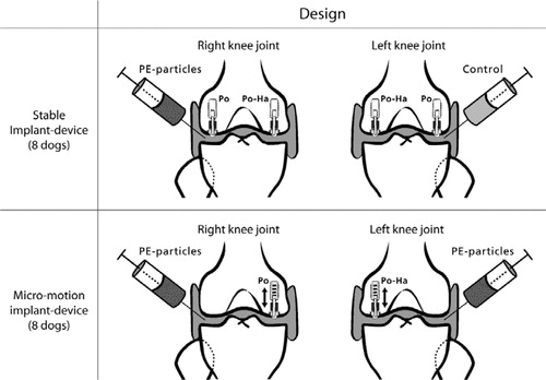
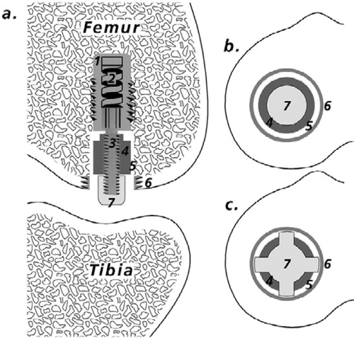
Figure 2. Implant devices. a. Implant device and test implant positioned in the weightbearing part of the femoral condyle (modified from Søballe et al. (Citation1992b, Citation1993)). 1. Threaded anchorage screw fixed in bone. 2. In the micro-motion device, a spring allows the piston to move 500 μm vertically. At each gait cycle, the PE plug and the implant were displaced 500 μm by tibia. When the pressure on the plug was released, the implant and plug were repositioned by means of a spring in the anchorage screw. 3. Threaded piston, which is centralized in the drilled hole by the anchorage screw. 4. Test implant mounted on the piston. 5. Gap measuring 0.75 mm, between implant surface and trabecular bone. 6. Titanium ring inserted into the subchondral part of the condyle to prevent early tissue ongrowth to the polyethylene plug. 7. Protrusion of the polyethylene plug (diameter 4.5 mm), which transmits the load from the tibial part of the knee to the implant system. b. Stable implant devices. Appearance of the femoral condyle after implantation of the stable implant device. Note the gap between the PE plug and the titanium ring, which allows the joint fluid access to the bone-implant interface. c. Unstable implant devices. The PE plug used for the micromotion devices had four tabs measuring 1 mm2. The extensions were added to ensure only vertical movement in the system. There was a gap of 250 μm between the ring and the PE plug tabs. It was possible for joint fluid to gain access to the bone-implant interface between the tabs.
Unstable model. PO-HA implants and PO implants were inserted with a 750-μm periimplant gap in the distal femoral condyles by the use of an unstable implant device. A spring inside the anchorage screw allowed the implant to move 500 μm in the vertical axis of the implant. We injected a 5 mL solution of PE particles dispersed in sterile hyaluronic acid into both knee joints (). These dogs were also killed 16 weeks after surgery.
Injection procedure for PE particles. Intraarticular injections were started 3 weeks after surgery and were performed weekly thereafter. In total, the injection procedure was repeated 13 times per dog. Injections were performed using sterile technique while the dogs were under a short intravenous anesthesia (thiobarbital). The lateral and medial joint chambers each received 2.5 mL by parapatellar injection.
Characteristics of injected material
The polyethylene powder consisted of 100% pure crystalline high-density polyethylene (HDPE) ([insert name whereabouts of manufacturer]). The particle size distribution was determined by scanning electron microscopy (SEM) (Cambridge S360) using automatic image analysis equipment. The analysis was performed at the Danish Technological Institute. The particles were spherical and the mean equivalent circle diameter was 2.09 (0.2–11) μm. 7% of particles in the powder had a diameter below 1 μm.
The particles were gamma-sterilized. Immediately before use, the they were suspended in sterile hyaluronic acid (1.75 mg hyaluronic acid per ml phosphate-buffered saline, pH 7.4) and mixed in a vial. The vial was then placed in an ultrasound bath for 30 min to homogenize the suspension. The suspension contained 5 mg HDPE (approximately 1.2 ×10⁹ particles) per ml hyaluronic acid, in accordance with our previous studies (Rahbek et al. Citation2000, Citation2001). We did not quantify loss of particles in the needle, but we considered this to be negligible.
Particles and hyaluronic acid from the original vials and vials used for mixing were analyzed by gas chromatography-tandem mass spectrometry to detect trace levels of lipopolysaccharide (endotoxin) (Szponar and Larsson Citation2001). No biochemical markers for endotoxins were found.
Characteristics of test implants
The cylindrical titanium alloy (Ti-6-Al-4V) implants (height: 9 mm, diameter: 6 mm) had a plasma-sprayed porous surface. The mean roughness (Ra) of the porous titanium surface was 26 (SD 3) μm and 17 (SD 3) μm for the HA-coated version. Analyses for roughness were performed at the Danish Technology Institute and done on 5 implants of each kind. Four longitudinal measurements were performed on each implant with 90 degrees between the measurements. A stylus with a tip radius of 2 μm without skid was used. The cut-off filter was 0.8 mm and the evaluation length was 4.0 mm per measurement.
The porosity of the coating was determined by the manufacturer (reflected light microscopy and automatic image analysis) to have a mean value of 33% (15–49). The HA coating was plasma-sprayed (thickness 50 μm, crystallinity 68% and purity 99%). The average porosity was 22% (7–34). To verify the measurements done by the manufacturer, we selected one implant with and one implant with-out HA coating for analysis of porosity by SEM with backscatter mode (Maxim 2040S, CamScan Electron Optics). Analysis was performed on successive 3-mm transverse sections of epoxy-embedded implants. Digital images of the total cross section of the implant were obtained with 171 pixels per mm. The coating region of interest (ROI) was defined by two circles. An inner circle excluded the core-substrate of the implant and an outer circle defined the periphery of the coating. Porosity was defined as area of void spaces (plastic) in percentage of the total area of ROI, and analysis was done by gray-scale threshold with image analysis software (ImageJ). The average porosity of the HA-coated and the non-HA-coated porous implants was 27% (range 25–30) and 44% (range 42–46). These figures agree with those given by the manufacturer.
The implants were sterilized by gamma irradiation.
Surgical techniques
The implants were inserted using sterile technique, while the dogs were under general inhalatory anesthesia with isoflurane. The knee joint was exposed using the subvastus approach (Hofmann et al. Citation1991, Matsueda and Gustilo Citation2000). Low-speed drilling and cooling with saline water was used to avoid thermal trauma of the bone. A 7.5-mm hole was created in the femoral condyle, leaving a 0.75-mm gap around the implants. The cavity was cleared of bone debris by the use of physiological saline. After the anchorage screw was inserted, the implant and polyethylene plug were mounted on the piston. The knee was tested after implantation, to ensure free motion of the knee joint. In dogs with unstable implant devices, free motion of the PE plug and test implant in vertical direction was also checked. The polyethylene plug protruded slightly above the cartilage, so a load was transferred through the implant system at each gait cycle (). Prophylactic antibiotics (ampicillin) were administrated immediately before surgery. Analgesics (Fentanyl plaster) were used on the first three post-operative days. Unrestricted weight bearing was allowed postoperatively.
Specimen preparation
The distal femoral condyles were cleared of soft tissue and stored at –20°C. Bone-implant specimens were divided with a water-cooled diamond blade (Exact Appartebau, Norderstedt, Germany) (). One-half of the specimen remained undecalcified. It was dehydrated in graded ethanol (70–100%) containing basic fuchsin (0.4%) and embedded in methylmethacrylate (Merck, ref 8.0590.1000) with 20% DPG-softener and 3% Pergadox. Serial vertical sectioning was performed on a microtome (KDG-95; MeProTech, the Netherlands) with 350 μm between sections (Baddeley et al. Citation1986). The sections were approximately 35 μm thick and they were counterstained with 4% light green (Gotfredsen et al. Citation1989). These sections were used for estimation of particle migration, tissue ongrowth and gap healing.
Figure 3. Preparation of bone-implant specimens. The cylindrical implant was cut vertically through the middle. By random choice, one-half remained undecalcified and was embedded in MMA. The other half was cut vertically through the middle of the implant. A posterior and anterior block were thus produced, each containing one-quarter of the implant. By random choice, one part was stored in formaldehyde and decalcified (EDTA). The implant was gently removed from the surrounding tissue, which was then embedded in paraffin. The remaining part was stored in 70% alcohol for a possible later analysis, which was not included in this work.
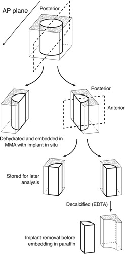
One-quarter of the bone-implant specimen was stored in formaldehyde and decalcified (EDTA). The implant was gently removed mechanically from the surrounding tissue, which was paraffin embedded. 7-μm-thick sections were cut serially, with 200 μm between sections, and stained with HE. The morphology of the peri-implant tissue was analyzed on these sections.
Histology
Morphology of the peri-implant tissue
Inflammatory response at the interface was graded from 0 to 3 in a blinded fashion by a pathologist, as previously described (Rahbek et al. Citation2000). The rating was done on 4 HE-stained sections per implant, without the use of polarized light to prevent the observer from being biased by the presence of particles. Grade 0 signified no inflammation present and grade 3 signified sections with confluent chronic inflammatory response dominating the interfacial tissue.
Histomorphometry
A stereological software program was applied (CAST-Grid; Olympus Denmark A/S, Denmark) for histomorphometry as in earlier studies (Rahbek et al. Citation2000, Citation2001). Unbiased estimates of bone ongrowth could therefore be calculated by stereological methods, even though cancellous bone is anisotropic (Gundersen et al. Citation1988, Overgaard et al. Citation1998b). A mean of 4.3 (3–7) sections were counted per implant. The variance introduced as a result of the section level was thus reduced to a minimum compared to biological variance (Overgaard et al. Citation2000).
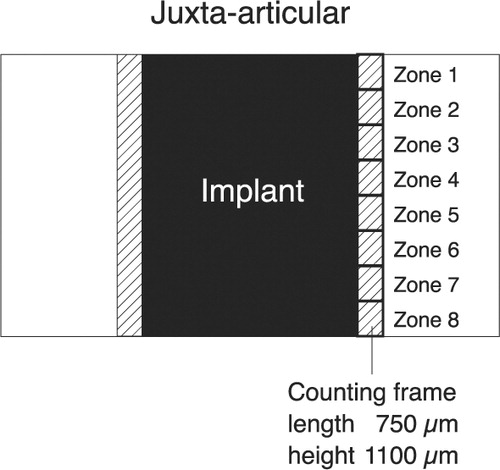
Migration of PE particles was evaluated by use of a counting frame (750 × 1100 μm) (Rahbek et al. Citation2000). This was aligned to the implant surface and the peri-implant tissue approximately 750 μm from the surface was analyzed. The peri-implant tissue around the implant was divided into eight zones with a height of 1100 μm (). A birefringent dot or flake was defined as a PE particle. The number of PE particles inside the counting frame was defined according to a grading system (CitationRahbek et al. 2000). Grade 0 was used if no particles were present inside the counting frame. Grades 1, 2, 3 and 4 were used when 1–10, 11–20, 21–50 or over 50 particles were present, respectively.
Figure 4. This simplified diagram shows a histological section with an implant. The counting frame is moved stepwise from the juxta-articular tip of the implant to the base of the implant, thus dividing the peri-implant area into eight zones. The initial peri-implant gap around the implant is indicated.
Ongrowth was defined as implant surface covered by bone, bone marrow, fibro-cartilage or fibrous tissue using the linear intercept technique. Approximately 227 (135–372) and 236 (141–360) intersections were counted per implant for stable and unstable implants, respectively.
Gap healing was defined as percentage of the initial gap filled with bone, cartilage, bone marrow or fibrous tissue, and was estimated using point-counting technique with a mean of 480 (121–858) and 473 (228–714) points per implant for stable and unstable implants, respectively. The 750-μm area adjacent to the implant surface was analyzed.
Statistics
We used SPSS 10.0 statistical software. The data were not found to follow a normal distribution. Wilcoxon’s signed rank test or Mann-Whitney U test was therefore used. Two-tailed p-values below 0.05 were considered significant. Median values and range are presented. Statistical analyses between stable and unstable implants were not performed due to differences in PE plug design ().
Results
Morphology of bone-implant interfaces
Stable implants
During the preparation of decalcified sections, we experienced some technical difficulties. Implants which had ongrowth of fibrous tissue could hardly be removed from the specimen, even after decalcification. The membrane was more strongly attached to the implant than to the surrounding bone. This problem led to the loss of one interfacial tissue sample for analysis at the cellular level in the PO-HA implants/+PE group. Two other interfacial tissue samples were lost for analysis, one from the group of PO implants/+PE, and one from PO implants/-PE.
There was no difference in the ratings of chronic inflammation in the bone-implant interfaces between groups. The ratings ranged from 0 to 2 with a median score of 0 in all groups.
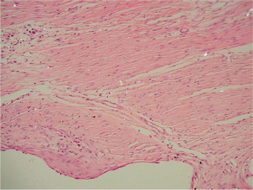
A fibrous membrane surrounded most PO implants; however, 5 of 16 PO implants showed areas of ongrowth of bone. PO-HA implants were surrounded by trabecular bone and marrow. Small areas of inflammation could be detected around some implants. There were no signs of marrow necrosis.
Unstable implants
The fibrous membrane surrounding one PO implant was damaged during implant removal and was lost for detailed cellular analysis. The inflammatory response around the two types of coating did not differ. Both groups were graded 0 (0–2). Mild or moderate inflammation was found around 3 implants in each group. A fibrous membrane containing PE particles covered the PO implants (). Surrounding the membrane, a bone-rim was found with a high level of both resorptive and formative surfaces.
Figure 5. Fibrous membrane from an unstable PO implant. Hematoxylineosin stained section viewed with polarized light; 200 × The void down to the left represents the original placement of the porous implant. Birefringent PE particles can be seen scattered in a fibrous membrane dominated by fibroblasts. Only a few macrophages can be seen in the membrane.
PO-HA implants were mainly surrounded by immature bone and bone marrow. Fibrous tissue was almost a constant finding in the areas showing loss of coating; however, fibrous tissue was also seen in areas with intact HA coating. Islands of fibro-cartilage were a typical finding within the fibrous tissue around PO-HA implants.
Migration of particles
Stable implants
The rating of the total number of particles in the total interface was reduced by the HA coating from grade 2 (1–4) to grade 1 (0–1) (p = 0.01).
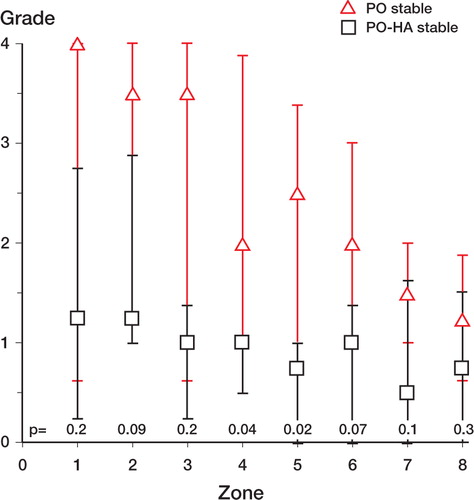
We found fewer particles around PO-HA implants in the mid-implant zones 4 and 5, as compared with PO implants (). The number of PE particles around PO implants was graded high in the zones near the joint space. There was a tendency towards less particles in the zones at the base of the implant, but without any significant difference between zones 1 and 8. HA-coated implants were graded approximately 1 in all zones.
Figure 6. Stable implants. Distribution of PE particles in peri-implant zones (compare with ). Median values. Error bars represent interquartile range. Zone 1 is the zone closest to the joint space. P-values are given in the figure.
Unstable implants
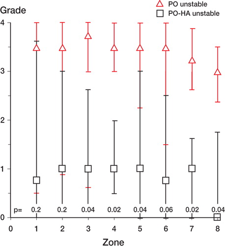
The HA coating reduced the rating of particles from 3 (2–4) around PO implants compared to 1 (0–3) (p = 0.002) around PO-HA implants. Around the PO implants, a fibrous membrane with huge amounts of particles surrounded the entire implant (). In most cases, HA-coated implants were sealed off from the joint space by either bone or fibro-cartilage at the juxta-articular tip of the implant. The ratings of PE particles in peri-implant zones 1–8 around unstable PO-HA implants were at the same levels as around stable PO-HA implants (median values 0–1). There was a trend towards more particles around unstable PO implants than around stable PO implants. Significantly, more particles were found around PO implants than around PO-HA implants in periimplant zones 3, 4, 5, 7, and 8 (). For stable implants, a corresponding difference only occurred in 2 mid-implant zones ().
Figure 7. Unstable PO implant. MMA section with the implant stained in situ with basic fuchsin and light green. Polarized light microscopy, 200 × Microscopic field of the fibrous membrane at zone 4. Multiple PE particles are scattered in the tissue. Note the absence of fibro-cartilage and bone.
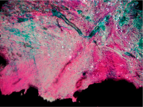
Figure 8. Unstable implants. Distribution of PE particles in peri-implant zones (compare with ). Median values. Error bars represent interquartile range. Zone 1 is the zone closest to the joint space. P-values are given in the Figure.
Ongrowth and gap healing
Stable implants
The presence of PE particles in the joint or in the bone-implant interface did not alter the tissue ongrowth or gap healing compared with control implants. PO-HA implants had signicantly higher values of bone ongrowth and less coverage of fibrous tissue compared with PO implants. The volume of fibrous tissue in the peri-implant gap was significantly reduced by the HA coating, but no significant differences existed for bone in the gap (Table).
Tissue ongrowth and gap healing for stable implants and unstable implants. The median value (range) of bone and fibrous tissue in the 6 experimental groups (n = 8)
None of the PO-HA implants showed denuded surface areas indicating loss of HA coating.
Unstable implants
PO-HA implants had significantly more bone ongrowth (28%) than PO implants (0%). PO implants were mainly covered by fibrous tissue (Table). A mean of 22% of the surface of PO-HA implants had lost the coating, assuming full coverage of the implant at the time of implantation. One implant in particular contributed largely to this loss. It had lost 70% of the coating, and this area was covered by fibrous tissue.
PO implants and PO-HA implants had approximately the same bone volume in the gap. Around PO-HA implants, a trend towards more fibro-cartilage was found compared to PO implants; but this finding was not statistically significant (p = 0.07).
Discussion
We found more PE particles around porous-coated implants than around porous-coated implants with additional HA-coating, under both stable and unstable conditions. The effect of the HA coating was more pronounced in unstable implants. To our knowledge, only one earlier experimental study (Kraemer et al. Citation1995) has compared the sealing effect of a plasma-sprayed porous-coated surface with an HA-coated surface. This study was conducted in dogs using a hemi-arthroplasty model and PE particles were injected into the hip joint one month after surgery, and this was repeated every month. The authors found an equal sealing effect in HA-coated, porous-coated and cemented implants within the 5-month limit of the study, as no particles were found around any of these implants.
The contradictory results in our study, with a superior sealing effect of HA, may be due to the initial peri-implant gap which delays bone healing around the implants. Furthermore, injections of particles were conducted earlier after surgery in our study, and repeated on a weekly basis instead of monthly. We found it important to mimic the continuous production of particles with small intervals between injections, allowing particles to accumulate in the interface. In the study by Kraemer et al., particles may have been transported away from the interface by the lymphatic system before new particles had time to enter, due to the long intervals between injections and a relatively low particle dose. Thus, any difference in sealing effect between HA implants and porous implants might not have been detected.
The sealing effect of porous-surfaced implants (Bobyn et al. Citation1995) can be explained by the osteo-conductive properties of the coating providing the implant bone ongrowth. This means that the porous structure serves as a passive scaffold, which enhances and supports bone ongrowth and seals off the interface. However, another explanation could be that the roughened surface of the implants may influence the dynamics of the joint fluid around the implants, thus providing a more stable environment at the interface. This hypothesis is supported by data from tissue ongrowth. In previous studies, we have found almost no bone ongrowth to grit-blasted Ti-6-Al-4-V implants after 8 and 52 weeks—using the same gap size and model as in the present study (Rahbek et al. Citation2000, Citation2001). Ti-6-Al-4-V implants were almost completely surrounded by fibrous tissue. This is rather unexpected, since the implants were stabilized by an anchorage screw and thus optimal conditions for healing were present. In the present study we found bone ongrowth of up to 32% around 5 of 16 porous-surfaced Ti-6-Al-4-V implants after 16 weeks. The different healing response around porous-coated Ti-6-Al-4-V implants compared with grit-blasted Ti-6-Al-4-V implants cannot be explained by the osteocondutive properties of the porous coating, since at the time of implantation the implant had no contact with the surrounding bone. However, our model allows joint fluid access to the bone-implant interface. Thus, the difference in bone ongrowth may be due to less fluid flow at the interface around porous-surfaced implants. In this way, porous-surfaced Ti-6-Al- 4-V implants could also contribute to the sealing effect by reducing the migration of particles carried by the joint fluid.
In earlier studies (Rahbek et al. Citation2000, Citation2001), we explained the sealing effect of HA by increased bone ongrowth to implants and increased fraction of bone in the initial gap surrounding the implants. HA simply prevented the fibrous membrane surrounding the Ti-6-Al-4-V implants. In the present study of unstable implants, we have a different situation. There was no significant difference in the gap healing around HA-coated and Ti-6-Al-4-V implants. The sealing effect must therefore lie in the thin bone trabeculae sprouting from the HA surface resulting in superior bone ongrowth compared to the more fibrous covered Ti-6-Al-4-V implants.
A previous study by our research group has shown that HA-coated implants subjected to excess micromotion develop islands of fibro-cartilage around the implant, and that HA has the ability to convert fibrous tissue into bone by tissue differentiation—even in the presence of micromotion (Søballe et al. Citation1992a). This was also seen in the present study. Moreover, micromotion influenced the stability of the HA coating, as we found 22% of the implant surface to be lacking HA coating. In contrast, there was no delamination of the HA coating in the stable implants. Our results support the findings of Overgaard et al. (Citation1996, Citation1998a). These authors suggested that the loss of HA could be accelerated by micromotion. When the implant is subjected to micromotion, a fibrous tissue membrane of high metabolic activity develops (Søballe et al. Citation1993). This fibrous tissue membrane is dominated by fibroblasts and macrophages capable of phagocytosing HA (Murray and Rushton Citation1992, Søballe et al. Citation1993, Overgaard et al. Citation1998b). In addition, fluid flow is increased along the interface, leading to accelerated dissolution from changes in calcium and phosphate concentration.
Our study was mainly designed to detect differences in particle migration between PO-HA and PO implants under stable and unstable conditions. The effect of PE particles on ongrowth and gap-healing was only tested under stable conditions, and was not influenced by the presence of particles. Since micromotion implants without PE particles were not included in the study, we cannot make any conclusions regarding synergy between micromotion and PE particles. However, the histology of interfaces from unstable specimens was very similar to those of interfaces from stable implants regarding cellular response, where no inflammation or signs of osteolysis due to particles was found.
The lack of osteolysis and inhibition of bone ongrowth in our study can be explained by insufficiency of the applied implant model to produce osteolysis or by particle-related factors.We find the implant model to be clinically relevant for a number of reasons: it is weight-loaded, it takes micromotion into account, implants are inserted into trabecular bone, and the interface is continuous with the joint-space into which polyethylene particles are shed. Using a similar model in dogs, Bechtold et al. (Citation2001) have previously demonstrated a synergy between micromotion (500 μm) and PE particles, resulting in a more aggressive formation of membrane around a PMMA implant. In this study, PE-particles were applied directly into the peri-implant cavity during surgery, resulting in a much higher concentration of particles at the interface. When compared to the results of our present study, these results indicate that the biological response in the implant model used is dependent on particle dosage.
The biological response on wear debris depends on several variables besides the number of particles (Brooks et al. Citation2000), such as particle size (Green et al. Citation1998, Gonzalez et al. Citation1996), and contamination by endotoxins (Ragab et al. Citation1999, Daniels et al. Citation2000, Bi et al. Citation2001, Skoglund et al. Citation2002). Regarding size, the HDPE powder did contain submicron particles as found around loose implants (Shanbhag et al. Citation1994). Moreover, an inflammatory response has been shown experimentally in a previous study after only 6 weeks of stimulation by HDPE particles with approximately the same average size (2.03 um) as used in the present study (Allen et al. Citation1996). It is thus more likely that the number of particles in the interface in the present study was too low to generate a sufficiently high inflammatory response. Furthermore, it has been shown that endotoxin contamination of wear debris plays a key role in the pathogenesis of particle-mediated bone resorption in experimental studies (Skoglund et al. Citation2002). We used endotoxin-free carrier and particles, which may explain the absence of osteolysis in our specimens.
We found that a thin layer of HA as coating provides a better ongrowth of bone and protects the bone-implant interface against the migration of wear debris, relative to a plasma-sprayed porous coating. This effect is present under stable conditions and even more so during unstable conditions. These results may not be applicable to other types of porous coatings. Open-pore coatings, such as beaded or fiber mesh coatings, may behave differently. Studies comparing different porous coatings are therefore warranted.
The authors wish to thank Anette Milton and Jane Pauli for their technical expertise in preparing the histological sections. Dr. Niels Osterby Olesen, Earth Sciences, University of Aarhus performed the SEM. Biomet Merck Inc. kindly provided the implants. Smith and Nephew-Richards provided the particles. Dr. Lennart Larsson, Department of Medical Microbiology, Dermatology and Infection, Lund University, Sweden, performed the analysis of PE particles for endotoxins. This study was supported financially by the Danish Medical Research Council, the Danish Rheumatism Association, and the Institute of Experimental Clinical Research, University of Aarhus, Denmark.
No competing interests declared.
Related Research Data
- Allen M J, Brierley T J, Millett P J, Rushton N. The effects of particulate polyethylene at a weight-bearing bone-implant interface. A study in rats. J Bone Joint Surg (Br) 1996; 78: 32–7
- Anthony P P, Gie G A, Howie C R, Ling R S. Localised endosteal bone lysis in relation to the femoral components of cemented total hip arthroplasties. J Bone Joint Surg (Br) 1990; 72: 971–9
- Baddeley A J, Gundersen H J, Cruz-Orive L M. Estimation of surface area from vertical sections. J Microsc 1986; 142: 259–76
- Bechtold J E, Kubic V, Søballe K. A controlled experimental model of revision implants: Part I. Development. Acta Orthop Scand 2001; 72: 642–9
- Bi Y, Seabold J M, Kaar S G, Ragab A A, Goldberg V M, Anderson J M, Greenfiel E M. Adherent endotoxin on orthopedic wear particles stimulates cytokine production and osteoclast differentiation. J Bone Miner Res 2001; 16: 2082–91
- Bobyn J D, Jacobs J J, Tanzer M, Urban R M, Aribindi R, Sumner D R, Turner T M, Brooks C E. The susceptibility of smooth implant surfaces to periimplant fibrosis and migration of polyethylene wear debris. Clin Orthop 1995, 311: 21–39
- Brooks R A, Sharpe J R, Wimhurst J A, Myer B J, Dawes E N, Rushton N. The effects of the concentration of high-density polyethylene particles on the bone-implant interface. J Bone Joint Surg (Br) 2000; 82: 595–600
- Burke D W, O'Connor D O, Zalenski E B, Jasty M, Harris W H. Micromotion of cemented and uncemented femoral components. J Bone Joint Surg (Br) 1991; 73: 33–7
- Daniels A U, Barnes F H, Charlebois S J, Smith R A. Macrophage cytokine response to particles and lipopolysaccharide in vitro. J Biomed Mater Res 2000; 49: 469–78
- Emerson R H J, Sanders S B, Head W C, Higgins L. Effect of circumferential plasma-spray porous coating on the rate of femoral osteolysis after total hip arthroplasty. J Bone Joint Surg (Am) 1999; 81: 1291–8
- Gonzalez O, Smith R L, Goodman S B. Effect of size, concentration, surface area, and volume of polymethyl-methacrylate particles on human macrophages in vitro. J Biomed Mater Res 1996; 30: 463–73
- Gotfredsen K, Budtz-Jorgensen E, Jensen L N. A method for preparing and staining histological sections containing titanium implants for light microscopy. Stain Technol 1989; 64: 121–7
- Green T R, Fisher J, Stone M, Wroblewski B M, Ingham E. Polyethylene particles of a ‘critical size'are necessary for the induction of cytokines by macrophages in vitro. Biomaterials 1998; 19: 2297–302
- Gundersen H J, Bendtsen T F, Korbo L, Marcussen N, Moller A, Nielsen K, Nyengaard J R, Pakkenberg B, Sorensen F B, Vesterby A, et al. Some new, simple efficient stereological methods and their use in pathological research and diagnosis. APMIS 1988; 96: 379–94
- Hofmann A A, Plaster R L, Murdock L E. Subvastus (Southern) approach for primary total knee arthroplasty. Clin Orthop 1991, 269: 70–7
- Kraemer W J, Maistrelli G L, Fornasier V, Binnington A, Zhao J F. Migration of polyethylene wear debris in hip arthroplasties: a canine model. J Appl Biomater 1995; 6: 225–30
- Matsueda M, Gustilo R B. Subvastus and medial parapatellar approaches in total knee arthroplasty. Clin Orthop 2000, 371: 161–8
- Murray D W, Rushton N. Mediators of bone resorption around implants. Clin Orthop 1992, 281: 295–304
- Overgaard S, Søballe K, Josephsen K, Hansen E S, Bünger C. Role of different loading conditions on resorption of hydroxyapatite coating evaluated by histomorphometric and stereological methods. J Orthop Res 1996; 14: 888–94
- Overgaard S, Lind M, Glerup H, Bunger C, Søballe K. Porous-coated versus grit-blasted surface texture of hydroxyapatite-coated implants during controlled micro-motion: mechanical and histomorphometric results. J Arthroplasty 1998a; 13: 449–58
- Overgaard S, Lind M, Josephsen K, Maunsbach A, Bünger C, Søballe K. Resorption of hydroxyapatite and flourapatite ceramic coatings on weightbearing implants: A quantitative and morphological study in dogs. J Biomed Mater Res 1998b; 39: 141–52
- Overgaard S, Søballe K, Gundersen G. Efficiency of systematic sampling in histomorphometric bone research illustrated by hydroxyapatite-coated implants: optimizing the stereological vertical-section design. J Orthop Res 2000; 18(2)313–2.1
- Ragab A A, Van De Motter R, Lavish S A, Goldberg V M, Ninomiya J T, Carlin C R, Greenfield E M. Measurement and removal of adherent endotoxin from titanium particles and implant surfaces. J Orthop Res 1999; 17: 803–9
- Rahbek O, Overgaard S, Jensen T B, Bendix K, Søballe K. Sealing effect of hydroxyapatite coating: a 12-month study in canines. Acta Orthop Scand 2000; 71: 563–73
- Rahbek O, Overgaard S, Lind M, Bendix K, Bunger C, Søballe K. Sealing effect of hydroxyapatite coating on peri-implant migration of particles. An experimental study in dogs. J Bone Joint Surg (Br) 2001; 83: 441–7
- Schmalzried T P, Jasty M, Harris W H. Periprosthetic bone loss in total hip arthroplasty. Polyethylene wear debris and the concept of the effective joint space. J Bone Joint Surg (Am) 1992; 74: 849–63
- Shanbhag A S, Jacobs J J, Glant T T, Gilbert J L, Black J, Galante J O. Composition and morphology of wear debris in failed uncemented total hip replacement. J Bone Joint Surg (Br) 1994; 76: 60–7
- Skoglund B, Larsson L, Aspenberg P A. Bone-resorptive effects of endotoxin-contaminated high-density polyethylene particles spontaneously eliminated in vivo. J Bone Joint Surg (Br) 2002; 84: 767–73
- Søballe K, Brockstedt Rasmussen H, Hansen E S, Bunger C. Hydroxyapatite coating modifies implant membrane formation. Controlled micromotion studied in dogs. Acta Orthop Scand 1992a; 63: 128–40
- Søballe K, Hansen E S, Rasmussen H B, Jørgensen P H, Bünger C. Tissue ongrowth into titanium and hydroxyapatite-coated implants during stable and unstable mechanical conditions. J Orthop Res 1992b; 10: 285–99
- Søballe K, Hansen E S, Brockstedt Rasmussen H, Bunger C. Hydroxyapatite coating converts fibrous tissue to bone around loaded implants. J Bone Joint Surg (Br) 1993; 75: 270–8
- Szponar B, Larsson L. Use of mass spectrometry for characterising microbial communities in bioaerosols. Ann Agric Environ Med 2001; 8: 111–7
- Urban R M, Jacobs J J, Sumner D R, Peters C L, Voss F R, Galante J O. The bone-implant interface of femoral stems with non-circumferential porous coating. J Bone Joint Surg (Am) 1996; 78: 1068–81
- Vanderby R, Jr., Manley P A, Kohles S S, McBeath A A. Fixation stability of femoral components in a canine hip replacement model. J Orthop Res 1992; 10: 300–9